SOLVED Caesar Chorus troubleshooting

immi

New member
Hello,

this is the first guitar pedal I built and I have some problems.
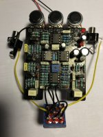
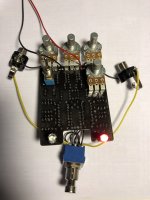
First of all the out of the four leds only two work. Of the two small leds, only the top one works (hard to see in the picture), and out of the two bigger ones only the right one works (constantly on). I get a Chorus effect with a very fast rate with all the pots turned down and nothing changes when turning any of them up. So the effect is always the same. Also when the effect is turned on, the bigger led is off.
Some additional info: I set the trim pot to around 6V and already resoldered most components.
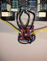
Let me know if you require a detailed view of any component.

Thank you, I appreciate any help
 

Attachments

  • IMG_4926.JPG
    IMG_4926.JPG
    429.9 KB · Views: 56
  • IMG_4929.JPG
    IMG_4929.JPG
    352.9 KB · Views: 56
Is the back of your Blend pot insulated from the board? If not, that can be causing multiple shorts and connections that aren't intended to be made.
You'll also want to ensure that your transistors are all making proper contact in the sockets. Lightly crimping the legs can help with this
 
Is the back of your Blend pot insulated from the board? If not, that can be causing multiple shorts and connections that aren't intended to be made.
You'll also want to ensure that your transistors are all making proper contact in the sockets. Lightly crimping the legs can help with this
The pots are insulated and the transistors seem to make proper contact, would soldering them directly onto the pcb be better?
 
The pots are insulated and the transistors seem to make proper contact, would soldering them directly onto the pcb be better?
I would suggest soldering them directly. The sockets can cause issues with connectivity, and I never use them for transistors.

Also, I noticed your 3207 doesn't appear to be a Cool Audio chip - was that sourced from a reputable shop?
 
I soldered the transistors directly onto the pcb now and set the bias back to 4.5V but everything is still the same as before.

Is there anything else i can check?
 
You should give every spot a re-solder. Just to make sure. When I have a build that isn’t fully operating, that’s usually step one.
Pop the IC’s out, first. And double check the orientation of the LEDs. I still mess them up occasionally.
 
Perhaps try biasing by ear, rather than by numbers. There's a narrow range on the trimmer where the chorus functions and you might try to find this before reflowing the entire board.
 
Ok guys thanks for the help, I checked the solder joints again, they seem fine and there seem to be no bridges. I guess I need to read up on audio probing.
 
Perhaps try biasing by ear, rather than by numbers. There's a narrow range on the trimmer where the chorus functions and you might try to find this before reflowing the entire board.
I just tried but the chorus sounds completely the same when turning in either direction.
 
I’m some what confused by your switch wiring hard to tell because it’s all black but it looks like you have the out where the in goes and in where the out goes. But I could be wrong it’s hard to tell. I wouldn’t expect you to get any audio when the effect is engaged if that’s the case.


This is not a good first build choice btw, it’s a lot of components with a lot of room for error and then having to track down an error in so many components makes it all the more challenging.

That being said, and not trying to be rude in saying that.

So are you saying as you turn the bias trim pot it sounds the same no matter the setting? That doesn’t make sense. This effect you should literally lose signal on the far sides of the bias trim. And only have a chorus effect for a small range ussually somewhat near the middle.
 
Ok guys thanks for the help, I checked the solder joints again, they seem fine and there seem to be no bridges. I guess I need to read up on audio probing.
I have tried to find a basic troubleshooting guide on the site. I seem to remember there is one somewhere but it eludes me for now.

A systematic process of elimination will at least narrow down the problem with any luck.

So, first off double-check you have all correct values of resistors and caps and tick this off. Check for any inadvertent solder bridges while you’re at it (already taken care of as you say). Look at the orientation of D1 and D2 as well.

If the board checks out in these two respects, let’s assume that you have done this correctly. Then the problem lies either with the offboard wiring (connections to footswitch) or the chips. Try bypassing the switch and see if you get audio with the in and out connections connected directly. It may be that you’ve reversed in and out or connected tip to ground or vice versa. No insults intended, just trying to be systematic about this.

If no change ensues from these steps, check your voltages with a DMM. I have a set of working voltages for comparison purposes which I’ll upload for you just now. If yours are wildly off, then the problem may lie with misaligned or faulty chips (not very likely).

Next step is making an audio probe and trying that. Let’s try to get your pedal working come what may…
 
I’m some what confused by your switch wiring hard to tell because it’s all black but it looks like you have the out where the in goes and in where the out goes. But I could be wrong it’s hard to tell. I wouldn’t expect you to get any audio when the effect is engaged if that’s the case.


This is not a good first build choice btw, it’s a lot of components with a lot of room for error and then having to track down an error in so many components makes it all the more challenging.

That being said, and not trying to be rude in saying that.

So are you saying as you turn the bias trim pot it sounds the same no matter the setting? That doesn’t make sense. This effect you should literally lose signal on the far sides of the bias trim. And only have a chorus effect for a small range ussually somewhat near the middle.
I checked the switch wiring again, should be right. I assumed that the switch has no orientation.
Yes I think I'm going to double check everything again and if it still doesn't work I'll come back to it some other time.
 
I checked the switch wiring again, should be right. I assumed that the switch has no orientation.
Yes I think I'm going to double check everything again and if it still doesn't work I'll come back to it some other time.
I checked the switch wiring again, should be right. I assumed that the switch has no orientation.
Yes I think I'm going to double check everything again and if it still doesn't work I'll come back to it some other time.
The switch only works one way round. The silver bit that joins the switch assembly should be horizontal (bit hard to see from your pics).

Try a continuity test to see if you get clean signal in bypass. If not, then it may well be that your switch wiring is off. Check against the wiring document in the build guide for confirmation.

Should go, with lugs face up: jack input to lug 2 (left middle), board input to lug 1 (left top), lugs 3 and 9 joined. Jack output to lug 8 (right middle), board input to lug 7. Lugs 4 (sw) and 5 (ground) enable the bypass LED. PPCB wires lug 6 to lug 1 as a precaution against noise in bypass mode.

Here are the voltages as promised. Ignore the one that says 'yours' (someone else's build).

YoursMine
IC1 (TL022)(TL062 subbed)
Pin 1: 0.65 - 7.86Varies0.764 - 5.685
Pin 2: 4.08 - 4.474.33.99 - 4.12
Pin 3: 1.46 - 6.59VariesVaries
Pin 4: 000
Pin 5: 4.05 - 4.454.33.96 - 4.17
Pin 6: 4.574.33.96 - 4.17
Pin 7: 1 - 6VariesVaries
Pin 8: 8.528.58.12
IC2 (RC4558)
Pin 1: 8.7363.88
Pin 2: 8.6963.89
Pin 3: 8.7463.89
Pin 4: 000
Pin 5: 8.7563.89
Pin 6: 8.7463.89
Pin 7: 8.7063.89
Pin 8: 8.758.88.23
IC3 (V3207D)
Pin 1: 000
Pin 2: 3.8943.89
Pin 3: 7.775.23.12
Pin 4: 7.9587.58
Pin 5: 8.538.68.15
Pin 6: 3.793.93.88
Pin 7: 7.906.53.65
Pin 8: 7.896.53.65
IC4 (V3102D)
Pin 1: 8.538.68.15
Pin 2: 3.793.93.88
Pin 3: 000
Pin 4: 3.8943.92
Pin 5: 0.800.80.390
Pin 6: 7.547.67.59
Pin 7: 2.642.92.34
Pin 8: 7.9587.57
 
The switch only works one way round. The silver bit that joins the switch assembly should be horizontal (bit hard to see from your pics).

Try a continuity test to see if you get clean signal in bypass. If not, then it may well be that your switch wiring is off. Check against the wiring document in the build guide for confirmation.

Should go, with lugs face up: jack input to lug 2 (left middle), board input to lug 1 (left top), lugs 3 and 9 joined. Jack output to lug 8 (right middle), board input to lug 7. Lugs 4 (sw) and 5 (ground) enable the bypass LED. PPCB wires lug 6 to lug 1 as a precaution against noise in bypass mode.

Here are the voltages as promised. Ignore the one that says 'yours' (someone else's build).
Thanks for all the info, I'm definitely going to check everything.
But I think there was a mixup with the 33K resistors I got sent, they were labeled with 33K but are actually 330K. I will get new ones and then check the rest.
 
The switch only works one way round. The silver bit that joins the switch assembly should be horizontal (bit hard to see from your pics).

Try a continuity test to see if you get clean signal in bypass. If not, then it may well be that your switch wiring is off. Check against the wiring document in the build guide for confirmation.

Should go, with lugs face up: jack input to lug 2 (left middle), board input to lug 1 (left top), lugs 3 and 9 joined. Jack output to lug 8 (right middle), board input to lug 7. Lugs 4 (sw) and 5 (ground) enable the bypass LED. PPCB wires lug 6 to lug 1 as a precaution against noise in bypass mode.

Here are the voltages as promised. Ignore the one that says 'yours' (someone else's build).
So I checked for bridges and the component values, both should be correct. The D1 and D2 Leds are oriented with the flat edge in the direction of the Cathode (labeled K on the pcb).

I switched out the mislabeled Resistors and the two bigger Leds are now working correctly. The D1 Led is still not working and the D2 Led is now pulsing on and off (don't know if it's supposed to do that).

I get a clean signal when the foot switch is in bypass.

I checked the voltages of the chips, wrote mine in the "Yours" side. I actually don't know if any thing is wrong with the chips because I can't interpret the voltages and I got sent a TL072 for IC1 (don't know if that changes anything).

Thanks for the help again.

YoursMine
IC1 (TL022) => TL072(TL062 subbed)
Pin 1: 1.30 - 7.34Varies0.764 - 5.685
Pin 2: 3.87 - 4.124.33.99 - 4.12
Pin 3: VariesVariesVaries
Pin 4: 000
Pin 5: 3.87 - 4.144.33.96 - 4.17
Pin 6: 4.064.33.96 - 4.17
Pin 7: VariesVariesVaries
Pin 8: 8.018.58.12
IC2 (RC4558)
Pin 1: 4.5263.88
Pin 2: 4.5363.89
Pin 3: 4.5163.89
Pin 4: 000
Pin 5: 4.5163.89
Pin 6: 4.5263.89
Pin 7: 4.5263.89
Pin 8: 8.328.88.23
IC3 (V3207D)
Pin 1: 000
Pin 2: 3.6043.89
Pin 3: 3.835.23.12
Pin 4: 7.4887.58
Pin 5: 7.988.68.15
Pin 6: 3.543.93.88
Pin 7: 3.996.53.65
Pin 8: 4.026.53.65
IC4 (V3102D)
Pin 1: 7.988.68.15
Pin 2: 3.533.93.88
Pin 3: 000
Pin 4: 3.5843.92
Pin 5: 0.700.80.390
Pin 6: 7.167.67.59
Pin 7: 2.522.92.34
Pin 8: 7.4587.57
 
Progress, if the LEDs now light up, I think.

I don't know whether or not the 072 should make a difference. AFAIK the 022 and 062 are low current versions so you should still get something.

Your voltages look reasonable to me. 0.5 volts shouldn't make a major difference (famous last words).

Do you get any sound when the pedal's engaged? Try tweaking the trimmer really slowly one more time. There's a narrow band where the chorus kicks in.

In my build notes, I noted that 'TL062 or LM358 or NE5532 might be usable for TL022.' Can't remember where I got this info from TBH but might be worth subbing one or other of these for IC1.

Have you managed to do a continuity check on the footswitch yet?

Hang in there. Try the trimmer tweak and let us know if anything changes.
Yes when the pedal is engaged I get a Chorus effect but its very fast and turning any pot doesn't change the sound.

Turning the trim pot also doesn't change the sound.

I actually don't understand what I'm supposed to be checking regarding the foot switch (Sorry if that's a dumb question). I understand that im supposed to check the continuity but between which lugs? I get continuity from the cables going from pcb to foot switch and the cables connecting the lugs inside the foot switch have continuity too.

I tried taking a better picture of the foot switch, could you explain based on that.
 

Attachments

  • IMG_5097.jpg
    IMG_5097.jpg
    363.5 KB · Views: 8
Back
Top