Can someone please debug the worlds easiest problem here for me...

kylewetton

Active member
I'm a beginner and figured I'd take what I learned and make a simple two channel looper. This pedal actually works really well.
The only thing that isn't working here is the LED. It works with the switch (on/off) as long as both 1/4" inputs on the left side of the photo are empty. If either get a jack placed in them, the LED will turn off. I'm very new so hopefully there's an easy solve here? The resistor is a 330 ohm if that matters.
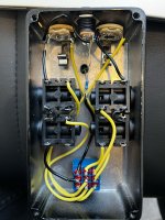
IMG_3301.jpg
 
Edit- Nevermind... my eyes were playing tricks on me :ROFLMAO:

Looks like your LED is solder to the wrong lug of the 9v jack. You'll want it connected to the bottom lug in your pic
 
Last edited:
My guess, those jacks are switchable. When you insert the cable, you break continuity on one lug.

I would find which lug always have continuity on the sleeve and go straight from that lug to the same lug on the next jack.

Edit : or bridge the sleeve lugs on every jack ?
 
My guess, those jacks are switchable. When you insert the cable, you break continuity on one lug.

I would find which lug always have continuity on the sleeve and go straight from that lug to the same lug on the next jack.

Edit : or bridge the sleeve lugs on every jack ?
I bridged them and it works, thanks for that
 
I bridged them and it works, thanks for that
Good, with testing, you would have found that the side of the jack where your audio signal is taken should be the direct connections and the other side of the jack shound be the switching side.

This can be used for example where you would have a two possible inputs and want that only one could be used at a time.
 
Back
Top