Yroc006
Member
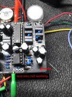
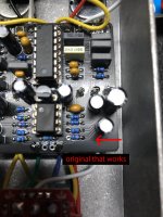
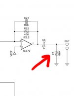
Hi there. Soooooo, I built one of these a few weeks ago, fired right up, love it, thought I'd build one for my brother. I finish up last night and there's no audio from the out pipe, bummer. Voltages all look good, cool. Start walking the tree with my audio probe and everything is going well until hit R7, which is especially frustrating since it's the last thing in line before the exit. Removed R7 to see if I was getting a signal to either one of the pads and i'm not, which confuses me. Looking at both boards side by side, I noticed a difference in the trace that comes out of the positive side of C6. My older working board looks like the picture on the product page, but the new board sort of looks like it's missing the trace from C6 to R7, which might explain the lack of signal. I tried a jumper to see if I could get signal to the resistor that way but it just goes to silence (my laymen's guess is it's going to ground), same if I jumper over R7 straight to the out pipe (just wanted to see what happens). So, i'm not entirely sure what to do here. I suppose I could just jumper out of C6 straight to the output, but that seems a bit sloppy, especially since I'm building this for my brother. I'm not electronically educated enough to know what R7 is doing exactly, but on my test rig with the guitar the other 99% of the circuit sounds correct. Any thoughts or ideas would be super helpful. Thank you!