harry_hood
New member
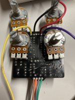
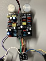
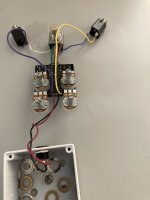
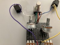
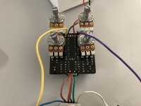
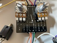
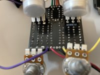
Hello all, I put together a cataclysm delay and could use some help on troubleshooting. It passes sound fine when bypassed and the led lights when on. I do get a faint, distorted echo and I can vary timing, repeats and create a self oscillation effect. But it will not pass the direct sound at all meaning essentially no output. I have gone over some of the easy stuff including verifying correct values, going over solder joints with magnifying glass, checked pots with multimeter, swapped out both the PT2399 and TL072. Any thoughts on specific parts of the schematic I might want to focus in on, or other next steps? Or maybe you see something obvious that I've missed? Thanks for any help!


")