- Build Rating
- 5.00 star(s)
This is the fourth Colorsound Power Boost or Overdriver build I've done. First was the Aion Plasma (9v Overdriver), then the Aion Nucleus (18v Power Boost), then the Madbean MeatQlaw. As I mentioned in the MeatQlaw writeup, when applying the waterslide decal, I initially overlooked the fact that the PCB was designed for a 1590B enclosure, and applied the decal to a 125B. I always planned to go back and make my own Power Boost PCB for a 125B with the same potentiometer orientation as the MeatQlaw. I finally got around to doing just that!
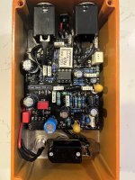
In my two most recent builds (here and here), I used PedalPCB's simple non-latching relay bypass. I love the simplicity of this bypass (commodity parts and no microcontroller), and it gave me the ah-ha moment that it decouples the actual circuit switching from the mechanical foot switch. Meaning, if I'm going to make a custom PCB, I might as well integrate the relay bypass. This allows for less offboard wiring, use of the "premium feel" soft-switch SPST switches, shorter signal cabling within the pedal, and a single PCB.
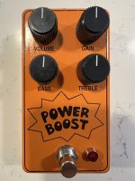
I just finished the pedal last night, only had time for a quick sanity test. But it first up and worked right away. I did a quick side-by-side comparison to my MeatQlaw, sounds more or less the same (but with the added satisfaction of using my own PCB). I sprung for a black board and the ENIG finish. I think it's a nice looking PCB. This is of course the second revision, I mentioned the prototype build here.
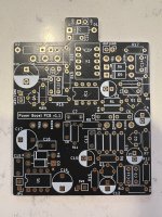
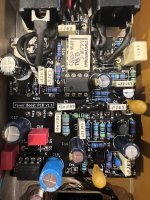
On the PCB, the actual component layout doesn't have the nice symmetry of PedalPCB boards. My main goals were isolating functional areas and minimizing track lengths and vias. Looking at the board, the lower-left is the LT1054 boost converter circuit; this area has a deliberate break in the ground planes between it and the right hand side, which is is the actual Power Boost circuit. The top and upper-right are the main power supply and relay bypass circuits.
Clearly I'm enamored with this circuit. I've actually had somewhat of an on-again, off-again relationship with it. I've come to the conclusion that it does require a little tweaking to get just-right. But it's also super-versatile. It works as a straight clean boost, and/or EQ; it can be used as a decent fuzz; can have the role of a treble booster; it can sorta do the edge-of-breakup thing... all while sounding very "vintage". In the lower gain settings, at bedroom volumes, there is a noticeable "splatty" decay to the notes (plenty of discussion about this all over the net). I can see how it would be a turn-off to some. I've actually grown rather fond of it, as it gives the guitar tone a hint of old-mediocre-recording vibe, or, as I like to think of it, vintage mojo. Either way, those artifacts aren't noticeable at louder volumes and/or in a band mix. One of my favorite uses recently is stacked into my Barber Gain Changer clone: I have the GC set for low-gain, edge-of-breakup, and the Power Boost drive set high enough to be a little fuzzy. As these guys demonstrate, the Power Boost really shines, almost demands, an amp that's already louder-than-bedroom-level. But I find with the GC in between amp and Power Boost, I can get satisfyingly close to the cranked sound at family-friendly volumes. Although I haven't really tried with other pedals, I suspect any pedal that stacks well, is reasonably transparent, and does a good edge-of-breakup thing would work well in the GC's place.
I'm giving myself five stars for this one. I got a little sloppy with the off-board wiring at the end, I was in a hurry to finish, but otherwise I think it's one of my better builds. For my next self-made PCB, I'm going surface mount. I'm also flirting with the idea of doing a four-layer board (I've thus far only ever made two-layer boards). Surface mount almost becomes a necessity when you start cramming lots of features into the circuit (relay bypass, 18v boost converter, and switchable buffered bypass would be nice too!); but I'd also like to be able to do top-mount jacks in a 1590B enclosure.
In my two most recent builds (here and here), I used PedalPCB's simple non-latching relay bypass. I love the simplicity of this bypass (commodity parts and no microcontroller), and it gave me the ah-ha moment that it decouples the actual circuit switching from the mechanical foot switch. Meaning, if I'm going to make a custom PCB, I might as well integrate the relay bypass. This allows for less offboard wiring, use of the "premium feel" soft-switch SPST switches, shorter signal cabling within the pedal, and a single PCB.
I just finished the pedal last night, only had time for a quick sanity test. But it first up and worked right away. I did a quick side-by-side comparison to my MeatQlaw, sounds more or less the same (but with the added satisfaction of using my own PCB). I sprung for a black board and the ENIG finish. I think it's a nice looking PCB. This is of course the second revision, I mentioned the prototype build here.
On the PCB, the actual component layout doesn't have the nice symmetry of PedalPCB boards. My main goals were isolating functional areas and minimizing track lengths and vias. Looking at the board, the lower-left is the LT1054 boost converter circuit; this area has a deliberate break in the ground planes between it and the right hand side, which is is the actual Power Boost circuit. The top and upper-right are the main power supply and relay bypass circuits.
Clearly I'm enamored with this circuit. I've actually had somewhat of an on-again, off-again relationship with it. I've come to the conclusion that it does require a little tweaking to get just-right. But it's also super-versatile. It works as a straight clean boost, and/or EQ; it can be used as a decent fuzz; can have the role of a treble booster; it can sorta do the edge-of-breakup thing... all while sounding very "vintage". In the lower gain settings, at bedroom volumes, there is a noticeable "splatty" decay to the notes (plenty of discussion about this all over the net). I can see how it would be a turn-off to some. I've actually grown rather fond of it, as it gives the guitar tone a hint of old-mediocre-recording vibe, or, as I like to think of it, vintage mojo. Either way, those artifacts aren't noticeable at louder volumes and/or in a band mix. One of my favorite uses recently is stacked into my Barber Gain Changer clone: I have the GC set for low-gain, edge-of-breakup, and the Power Boost drive set high enough to be a little fuzzy. As these guys demonstrate, the Power Boost really shines, almost demands, an amp that's already louder-than-bedroom-level. But I find with the GC in between amp and Power Boost, I can get satisfyingly close to the cranked sound at family-friendly volumes. Although I haven't really tried with other pedals, I suspect any pedal that stacks well, is reasonably transparent, and does a good edge-of-breakup thing would work well in the GC's place.
I'm giving myself five stars for this one. I got a little sloppy with the off-board wiring at the end, I was in a hurry to finish, but otherwise I think it's one of my better builds. For my next self-made PCB, I'm going surface mount. I'm also flirting with the idea of doing a four-layer board (I've thus far only ever made two-layer boards). Surface mount almost becomes a necessity when you start cramming lots of features into the circuit (relay bypass, 18v boost converter, and switchable buffered bypass would be nice too!); but I'd also like to be able to do top-mount jacks in a 1590B enclosure.