Erik S
Well-known member
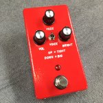
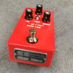
Corduroy / Wampler Velvet Fuzz.
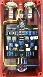
I was excited to play with my new hot air station, so I went with SMD J201s. Worked out okay, but definitely a challenge applying a small enough amount of solder paste for those tiny pads, and placing them with tweezers. Biased all three to 4.5v, and it sounds pretty good, so I didn't bother to go back and tweak them by ear.
A rare complaint for a PPCB board, but I didn't love this layout. The upside down three knob layout is weird, the lower pots were tricky to solder without melting the caps, and I ended up bending the upper pot out of the way to solder the upper ground and power wires. It always freaks me out a little when I see pics in troubleshooting threads with all the pots bent up off the board. I hated doing that, but it was better than desoldering it.
On the plus side, I like the sounds. This is my second JFET drive in a row, and I still have the GPCB Sabotage on my board, so I spent some time A/B testing the two. They have similar harmonic character, but the Sabotage is brighter, and the Corduroy is more open sounding, and has a lot more range. I much prefer the tight setting.


