Dead Minnow

churchmans

New member
Hello, this is my first post. Probably my 5th pedalpcb build but my first that didn’t work!

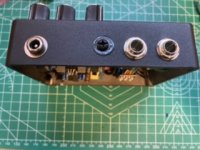
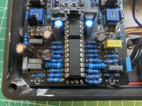
Finished a minnow but all I get is a bypassed signal. Blue led flashes for a second while plugging in but after that no leds.

Anything glaring? Any troubleshooting tips?

Thank you in advance for your help!
 
IC1
.9
.2
.1
.8
.1
.8
.8
9.5
IC2
8.4
0.2
0.2
0.8
1.7
2.0
2.2
9.5
IC3
.8
.5
.4
.3
.4
.8
.5
.8
.2
.2
1.2
.4
.2
.2
.5
.7
IC100
1.2
.1
.2
.6
.8
1.0
1.2
1.2
Q1
1.2
1.2
.4
Q2
.8
.2
.7
Q3
.5
.9
.4
Q4
1.3
1
2.3
Q5
2.0
1.2
1.2

This is my first time taking voltages and I hope this makes sense but they look vastly different from another members post.
I'm all ears for learning - any help is much appreciated.
Thanks in advance!
 
So my experience is going to prevent me from helping further. I just want to be transparent here those voltages dont seem to be right to me. I think someone whos better suited to help can give you a better answer and will know what to do from here.
 
Last edited:
Do the above readings help at all?
What can I do differently?
Thank you for your help.
How did you take them on the ICS? The pins are like this:
1 8
2 7
3 6
4 5

Down the left and up the right. The other ICs work the same way.


1663105953437.png

The transistor pins are numbered like this. I used a 5457 as an example, but the principle is the same for all transistor pin numbering.
 
Down the left and up the right. The other ICs work the same way.
Yes thats how I took the measurements - I listed them starting at 1 and going up numerically.
Here are new ones i took with a different DMM - pretty similar results.
Thanks again for trying to help!

IC1
.78
.06
0
.69
0
.66
.66
9.38
IC2
8.32
.06
0
.70
1.52
1.84
2.14
9.38
IC3
.58
.3
.28
0
.28
.70
0
.68
.05
0
1.12
0.28
.03
0
.30
.57
IC100
1.14
.01
0
.08
.68
.56
.11
.09
Q1
.13
.16
.20
Q2
.22
0
.21
Q3
.19
.68
.19
Q4
1.86
.83
1.05
Q5
.09
.12
.83
 
ic100 voltages look all wrong. pin 1 and pin 8 are tied together in the schematic so should be the same and should be around 9v. pin 5 should be around -9v and powers the other ics. without the correct voltages here nothing else can work. interestingly, the power pins on the other ics are getting 9v, just not ic100, so look to the soldering around ic100
 
Right away, the very beginning of your power section is screwy. As PJS mentioned, IC 100 Pin one and 8 should be about 9v. Pull the IC and measure the socket at those pins. If they measure 9, or close to it, look at changing the Charge pump, or look for possibe reasons it's shorting to ground, around those pins
 
Ah, Ok.
So even with the IC removed I'm still getting low voltages. I reflowed the solder for those sockets and cleaned around it with alcohol/qtip but still no change.
Where to go from here?
 
OK, I have one of these boards unpopulated. It looks as if the trace for pins 1 and 8 of IC100 comes from one end of R18. Check and see if one end of R18 has 9V, and also check for continuity from that end of R18 to Pins 1 and 8 of IC100
 
OK, I have one of these boards unpopulated. It looks as if the trace for pins 1 and 8 of IC100 comes from one end of R18. Check and see if one end of R18 has 9V, and also check for continuity from that end of R18 to Pins 1 and 8 of IC100
r18 is only reading .55 and 1.92v
But there is continuity between R18 and 1&8 of IC100.
 
The traces are so hard to see on a black board (probably deliberately I suspect). Anyway, just to change topics, where did you get your J201s? Most of the TO92 ones currently available are fake. At least one connects directly to 9V. A fake one could potentially muck around the voltages maybe?
 
The traces are so hard to see on a black board (probably deliberately I suspect). Anyway, just to change topics, where did you get your J201s? Most of the TO92 ones currently available are fake. At least one connects directly to 9V. A fake one could potentially muck around the voltages maybe?
I bought the j201's from guitarpcb.com and the receipt says "guaranteed genuine."

I can't thank you all enough for the help!
 
If you have voltage on Pin 8 of IC1 but not on IC100 there is likely a damaged trace.

Measure the voltage on Pin 3 of TRIM1 and the positive side of C101.
 
Back
Top