Chuck D. Bones
Circuit Wizard
This post describes the mods in the Col. Klink.
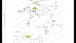
The EQD Warden is a good optical compressor. Basic design is mostly sound, with one major defect, one minor defect and a few opportunities for improvement. Parts of this design were lifted from the Ross compressor.
Major Defect
The signal path is routed through Q1, where is gets distorted by the non-linear loading from D2 & Q3. This is easily corrected by disconnecting C14 from Q1-E and connecting it to IC1 pin 1. You can do this on top of the board simply by lifting the + lead of C14 out of the pad and running a jumper to the end of R5 closest to IC1. I did it by cutting and jumpering on the bottom of the board. If you're not experienced in trace cutting, then do the mod on the top of the board.

Minor Defect
The bottom end of the TONE control is useless. I don't know about you, but I have no use for a treble cut in a compressor. A little treble boost brings the sparkle back that gets lost in compression. The stock tone control is flat at about 8:00 or 8:30 and below that cut treble. At 7:00 it's a very strong treble cut. Installing a 20K resistor in series with pin 1 of the TONE pot fixes that. Now 7:00 is flat and it's all treble boost above that. You can cut the TONE pot's lead short and install the 20K resistor between pin 1 and the board, or use a solder lug pot like I did.

Opportunities for Improvement
1. Q1 biasing. Q1 is biased close to saturation, which reduces its dynamic range. If we correct the major defect above, this mod is less important. However I wanted to maximize the performance of the envelope detector and remove any loading effect from the output of IC1.1. Replace C5 with a 3.3K resistor (stand it up). Replace R6 with a 10K resistor. Do not solder the bottom end (the end furthest from Q1) to the pad, solder it to the next pad over at the end of R7 (also 10K).

2. Better component values.
2a. Change R3 to 2.2M, change R1 to 2.2M or larger; I used 4.7M. R3 = 10M makes no sense when R1 = 1M. Change C2 to 100nF, 1uF is at least 10x larger than it needs to be, even with R3 reduced to 2.2M.
2b. Change R4 to 10K for 6dB more sustain.
2c. Change the LEVEL pot from B50K to A50K. Gets unity closer to noon.
Parts Substitutions
This is all very optional. I did it because I had the parts.
Q1-Q3 can be any high-gain NPN transistor. I used 2N5210. They can all be 2N5088, 2N5089, MPSA18, etc. Don't waste your best transistors here.
I used some fast rectifiers for D4 & D5 to improve the charge pump efficiency. 1N5817 is also a good choice.
I used TC7662 for IC2, it is slightly more efficient that the usual suspects.
A note about the LED & LDR.
I used a frosted white LED. It's very bright even at low current. It turned out to be overkill. The LDR I used is in a TO-18 can, obtained from Electronic Goldmine. They were dirt cheap on sale, like 40 cents each. One ot two stinkers in the bunch, but the rest went from under 2K (illuminated) to over 2Meg (dark). Cadmium Sulfide LDRs have a quick response to light, their resistance drops in a few milliseconds. Their response to dark is much slower, over 100ms to get from 2K to 500K. The more light that hit them, the longer it takes for the resistance to go up. That's why a bright LED isn't always a good thing. I find it best to set the ATTACK at 8:00 or 9:00 so the peak LED current is less and the release is quicker.


") Do You have comparision between Warden and ThorphyFX Fat General ?
Do You have comparision between Warden and ThorphyFX Fat General ?