Frustrating off-board wiring for Eva

spi

Well-known member
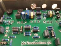
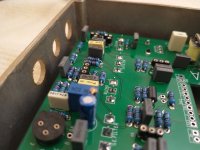
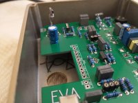
I've been building a Dead End FX Eva circuit. I put the holes for power and jacks off to one side to allow room for the Ge transistors. However, I neglected to notice that there are box caps there, so my hole locations won't work. Now I'm looking around for alternate locations, and I don't really see any on the back--there's obstacles all over the place. I can put them on the sides (yuck). but they would have to be located asymmetrically because the free space on each side are in different locations.

I might have to just pull the caps and mount them on the other side or other drastic measures.

Anyone build this before and have some advice?

IMG_20231028_132122411.jpg
IMG_20231028_132259832.jpg IMG_20231028_132251946.jpg
 
I have done a few deadend boards and yeah, this pretty common, even with the typically oversized boxes. One thing I usually try and do is make sure the drill template is down far enough so the pcb is almost touching the inside of the box on the switch side. Your best bet is to just lay those caps down or bend them out the way enough to fit the jack. Looking at your pics, you might be able to finagle the jacks (depending on which kind you are using) in there so long as the tip faces away from the caps, but even doing that, if you don’t lose transistor the sockets, you won’t have enough depth
 
Last edited:
Could that cap be mounted on the other side of the board ?

Edit : that may not clear the pots... offboard wiring if everything else fails!
 
This was, beyond a doubt, the most frustrating build that I have ever done. As you have discovered, the PCB does not seem to have been designed for use in an enclosure that also includes jacks. I ended up mounting a couple of the capacitors on the bottom of the board (with the leads bent, as @Nostradoomus described), and replaced the taller multi-turn trimmer with a shorter side-adjust one.* The jacks fit, but I had to sand down the lip of the enclosure so that it could shut. Here's a picture of what how I finally got the board and jacks to fit in the enclosure at the same time:
IMG_1078.jpeg
* Note that this makes it almost impossible to adjust the bias while the PCB is in the enclosure. (Due to frustrations with the bias trimmer, the awkward jack placement, and the sideways layout, I ended up building a second one with a PCB of my own design. But that's a story for another time.)
 
For those who have the board but haven't drilled holes in an enclosure for it yet:

Hammond 1590Q


It's the square version of a 1590BB's long side; however, it's not as deep.


DEPTH for comparison:
28mm 1590Q
30mm 1590BB
38mm 1590BBS
34mm 1590BB2
27mm 1590B
 
I decided to address the issue by getting a very spacious 1590XX enclosure. Now it fits easily. It's an unfinished enclosure so it's awaiting a spray can treatment and maybe some labelling or artwork, so offboard wiring is paused until I can get around to it.

IMG_20231125_112158412.jpg
 
As for the old enclosure, I am trying to patch it up using JB Weld. One of the many things I learned from this forum is that you can patch up holes and reuse enclosures. I was a bit skeptical it would work for me, but so far seems to be going ok.

Here's the enclosure after taping off the holes and stuffing the holes with the JB Weld epoxy putty.
IMG_20231124_150440407.jpg

Here it is the next day sanded pretty flat. I scuffed up all the powdercoat on all sides so I can apply a spray can color.

IMG_20231125_112227097.jpg


Here's the inside after I took off the making tape.

IMG_20231125_112233379.jpg


Next up I will drill the holes for a Duocast. I think at least some of the holes will overlap with the epoxy filled holes, so I'm nervous about the next part but hopefully it holds up to drilling.
 
Oh yeah, that stuff is where it’s at. I had to use it more than I care to admit. It sands down fantastic and painting over it looks great, too.
 
  • Like
Reactions: spi
Back
Top