Hi guys I’m new to pedal building and this is my 3rd build the gravitation reverb. I had populated the board and I wired it to jacks and stomp switch I had bypass when it’s turned off but when engaged I get no sound even though the led light turns on. Which leads me to believe the problem is on the circuit board yet I have looked at others boards and mine doesn’t look any different I don’t if my parts are low quality if that a thing but all of my polarities on my electrolytic capacitors are right both my ic chips are on correctly, I do use bojack resistors from a kit but I don’t know if that will affect anything I did notice the legs are a bit thinner but others other than that they’re all the right values. I checked my pots and they’re on correctly and I do have the right belton reverb chip soldered directly the only the thing different I could notice was the voltage regulator the pub calls for L78L05 but I have LM78L05ACZ I don’t know if that’s it I read somewhere that the pin out might be different but I’ve gotten 2 different answers yes and no lol. I’m lead to believe this is the problem. Can anyone help me out here I’ve ordered a 2nd board and reverb chip since I feel like the parts could be duds……oh and I forgot to mention because of that confusion about the voltage regulator I’ve removed and tried backwards and the same thing and now I e ruined the eyelets where it’s needs to go idk if it’s salvageable but I’ll be posting pics please help lol
My thoughts exactly I’m going to just wait for the new board to come and my new station comes in Sunday again I think with the new station I’ll be making better solder joints hopefully I feel like that along with damaging the eyelets of the regulator was the culprit Now that I have this new DMM I’m also going to be making sure all my components are right thank you guys for the support I will definitely be updating you guys in the next build!
Next time wait to install the Belton module until after you've tested the clean signal, it'll make it easier to get to the back of the PCB for any measurements if needed.
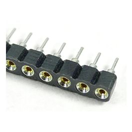
Quick question I just ordered these do they work similar to the other sockets in terms on orientation to the circuit board? Or I just have to be sure my voltage regulator is in correctly?
Quick question I just ordered these do they work similar to the other sockets in terms on orientation to the circuit board? Or I just have to be sure my voltage regulator is in correctly?
This is how the sockets work. Generally, semiconductors (diodes, transistors, and ICs) don’t like excessive direct heat from the iron. The socketing avoids this and means you can change parts as you need. In this case, we work from shortest component to tallest, beginning with resistors and diodes. You’ll want to see some solder on both sides of the board. There’s a moment when the solder flows easily and the right amount of time becomes a matter of experience (generally, two or three seconds works for me).
I tick each installed component off against the BoM, to make double-sure the right components go to the right slots. Easy enough with @PedalPCB’s boards since the component values are provided for you but still worth checking against the document to ensure that common mistakes are avoided from the start. I’m familiar with resistor colour codes, but still check (and label each part) in case of slips or a mispackaged part (very uncommon, but human mistakes do happen).
With diodes, I solder one leg at a time and give them a moment to cool down. Then, I’ll use the DMM to check they are functioning correctly (by checking forward voltages are within the ballpark). With the sockets, it’s worth tack soldering a leg or two first and then carefully pressing down with the iron to check they are level. Don’t spend too much time on this step; the plastic can melt quite easily.
Next, the caps.
Then, the elcaps in height order as you see here.
Next, offboard wiring (9V and ground, red and green), inputs and outputs (I use white and yellow to keep track). At this stage, I usually clean the board with Flux Off or some such. This gets rid of excess flux and any stray strands of wire which may cause shorts. You can also test the IC voltages at this point before installing them, as before DMM set to DC volts (black to ground and red probe to the appropriate pin) and check that the voltages in play are in the ballpark. The data sheet will tell you which pins to shoot for and roughly what voltages apply in each case.
Then, install the ICs after taking precautions against electrostatic discharges (wrist strap, and so on). Some might prefer doing these after the onboard pots, but whatever works for you. Try to avoid the temptation of spraying Flux Off too near the pots, so maybe use a cotton swab to remove flux near the pot legs if you are so inclined.
Next step is to test it out before boxing. I have a little test contraption which connects board in, board out, 9V, and ground on crocodile clips so you can test bypass and engaged functions at will. I kludge mount an LED (IOW, not soldered yet) to verify the board’s getting power and twist the ground and switch leads together temporarily to test this. If all is well, I’ll box it up and solder the jacks, power jack, switches, LED, what have you.
I guess everyone has different approaches to building but these basic principles work for me. YMMV. Good luck with the new build; let us know how you get on.
Hello, I’ve just finished building the Gravitation kit, but the pedal is making a strange sound. There is a faint sound when the pedal is bypassed (off), and it gets even louder when the pedal is engaged with the Mix control above zero... Do you have any idea what might be causing this issue?