Help please/ Debugging how to?

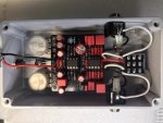
Ive got a pile of non working builds piling up. It seems for every one I get built another doesn’t work and I don’t know enough to get through them on my own. after an integral preamp I built today doesn’t work yet again I am pretty frustrated.

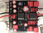
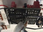
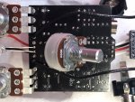
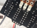
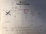
My integral is farting and distorting. I reflowed everything thrice. Then I swapped all the Electrolytics, one film I suspected, and the Q2 transistor. Still a farting crackling mess.

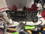
After blindy swapping 10 parts and no change I need help.

How do I learn to debug and use an audio probe??? I bought one but haven’t experimented yet.

getting so frustrated it makes me want to give this up at times.

I see some extremely talented people here helping others debug, I could use your help as well.

thanks!
 
Here's a PDF on the audio probe and how to use it from my Google drive


I'd also make yourself a test box you can get pcbs for one with an integrated audio probe or make your own,


with a test box you can test your circuit before boxing it if it works then doesn't when you've boxed it up you know you've made a mistake with your offboard wiring to jacks, 3PDT, DC jack etc It also saves you from soldering jacks etc to your pcb you simply connect your in and out power and ground and test away

The fault you describe on your pedal sounds like a mis biased transistor or the tl071 unfortunately there's more than one cause it could be incorrect value resistor, poor solder joint etc etc

I'm not familiar with this circuit but generally on your op amp you want half power supply on pins 2,3,6 ground on 4 and power to 7

Again generally on your transistors from 0.6v to just over 1v on the base middle pin or at least a small biasing voltage depending on what they're used for

The first thing I do for this type of fault is check what power you get to the board ie if it's 9v make sure you're getting 9v

You can also check all your VCC and VREF points indicated on the schematic

Then I'd visually check component values and orientation of polarized devices like diodes, electro caps, transistors etc

Check all your resistors by colour band and capacitors by the value printed on them

 
Last edited:
I posted this list on another forum. I'm no expert, and only have a few months and 20 builds under my belt so far, but I've had my share of non-starts, partially working, etc... builds. So I've picked up some great advice along the way and developed a step-by-step process to track down a problem. Feel free to ask questions on these!

It IS frustrating... until you figure out the problem. Then it's twice as rewarding... you built it, you fixed it. It's a good feeling. Unfortunately for some of us, we get that "double reward" much too often. Lol. A lot of good suggestions, but here is my troubleshooting process... it might help you get started.
Get a notebook and write down these steps as you go, and check them off. Helps to avoid backtracking.
  1. DOUBLE CHECK that you have 1. the guitar input and output cables oriented properly. (Yes. It happens. I have plugged the guitar into the output jack and the input to the amp.) 2. The CORRECT DC power applied. I have used 18V when it should have been 9V. Watch the power supply you're using. If it's a multi-output, make sure the output you're using is a 9V output; and 3. That you are using good cables and that all jacks are plugged in all the way.

  2. Double check that NOTHING else (besides the pedal) could be the issue. Go Guitar directly to the amp. Then go Guitar through a KNOWN GOOD pedal. This confirms your guitar, cables, and amp are NOT the problem.

  3. Evaluate what symptoms you have and how they relate... LED lights? Then you are getting power to the LED. That's all you know, but at least your DC jack, the LED, and most likely, the footswitch is installed correctly.

  4. LED works but no sound: In some pedals this can still be a reversed LED. In some pedals it doesn't relate.
    A. No LED, but pedal works. USUALLY a bad LED or a reversed LED that does not impeded voltage to the circuit.
    B. No LED and No Sound. this is usually in the power section somewhere. Bad LED, wrong value components in the power section, mis-wired DC jack or battery snap, etc...
    C. LED and sound but not the CORRECT SOUND. This is 9 out of 10 times something in the circuit that is the incorrect value, although in some cases a mis-wired in/out jack can cause this. When Have this symptom, I usually check OpAmps or Transistors first. Make sure they're seated properly, no pins are bent or broken, sockets are properly soldered, etc. Double check orientations and pin-outs (see step 5 Below), ESPECIALLY if you used an alternate part from the build docs.
    D. LOUD Hum or other "noises"... this is normally something mis-installed or mis-wired and it's putting ground or a stray DC voltage to the signal path. Audio Probe (see step 7 below) will help with this.

  5. Next you need to check for voltages where they should be. Make sure the V+ is getting from the switch onto the PCB. measure where the schematic says you should have "V+", "Vcc", or "Vref". Usually "Vref" is 4-5 volts where "V+" and "Vcc" indicate full 9V.

  6. Google the pinouts for your transistors and ICs The pinout paper should tell you which pin on the IC should have Vref . Check those. If you don't see it, use the schematic to help you find why it's not there.

  7. If all your voltages are good, then the most likely culprit is in/out jack wiring, or you got an incorrect component somewhere. Personal Example... I mis-read a schematic once and put a 510 OHM resistor where a 510K Ohm resistor should be - Improperly biased an OpAmp. No sound. So now is the time to check EACH resistor Color code, each Capacitor value, etc... If you find one that is off, figure out WHY it could cause the problem before you replace it. Not EVERY "wrong" component needs to the replaced right away. Nothing more frustrating that finding A problem, and then realizing it's not THE problem.

  8. If all the above fails, Audio Probe will be your best clue finder. It will tell you exactly where the sound IS and where it is NOT. When you find the spot where it stops, THEN you have to figure out what could cause that stoppage. It may not be obvious, but it gets you into the correct part of the circuit to be looking for the problem.

  9. TAKE NOTES! A lesson learned has very little value if you don't keep track of it. If you notice you frequently have wrong values, develop a process where you have a check list to tick-off as you install parts. I have now gone to reading EVERY resistor and Cap with a DMM as I install them, while checking off the list. Lessons Learned should make you compensate where you have issues.

  10. I keep these on hand for troubleshooting: Test Breakout Box w/ Breadboard (I built it). This also allows me to test my PCBs BEFORE I wire the switch, power jack, in/out Jacks. If it works on this, then doesn't work after boxing, it MUST be one of those things.; Audio Probe (I built it) with a Looper pedal (the looper "plays" chords as I probe. This keeps me from having to strum a guitar then probe as the note decays!); Good DMM that reads DC, AC, Ohms, Caps, Diodes; Transistor tester (I got a decent on from Amazon for $25. Only used it twice, but it's a HUGE help to eliminate transistors as a problem). With a tool set like this, you should be able to find any problem without the need for expensive tone-generators or Oscilloscopes.


Good luck!
 
I agree with everything above. Have your read through this thread yet? It won’t help you troubleshoot, but may help avoid problems in the first place / develop best practices.


I don’t personally use flux on the leases or IPA to clean, so it’s not absolutely necessary, But might be helpfulto make sure all your solder joints are good.
 
Visual inspection is your most powerful troubleshooting tool. The only skills it requires are patience and attention to detail. Tools are good light, good eyes and magnification. I'll wager that close to 90% of the posts in the Troubleshooting forum were or could have been solved by inspection.

Workmanship is the most likely cause of a pedal failure.
 
Much to read, watch and respond to. Thank you to ALL of you in advance.

I spent last night watching audio debug videos and learned to use my audio probe today. ?

I am not a novice with my iron, I go VERY slowly and methodically. I have a folder on each build full of notes etc. obviously I am human and still make mistakes. Ill try to get better at these things of course.

My resistors can be easily read once installed. I swapped out all the electrolytics, Q2, charge pump and opamp and collected some data and images which I will post. I see no wrong components or noticeable solder bridges/damage under magnification. IC sockets and pins look fine.

Charge pump:
1-8.5 8-8.50
2-3.8 7- 6.20
3-0.0. 6-4.00
4-0.0. 5- 0.00

opamp:
1-0.00 8-0.00
2-24.9 7-28.2
3-24.9 6-25.0
4-0.00 5-0.00
 
Last edited:

Attachments

  • 26DBB396-5342-4469-AABC-7A1462C8A94A.jpeg
    26DBB396-5342-4469-AABC-7A1462C8A94A.jpeg
    327.8 KB · Views: 27
  • 2DB54205-1A0E-48AF-890D-3554670EF748.jpeg
    2DB54205-1A0E-48AF-890D-3554670EF748.jpeg
    236.4 KB · Views: 31
  • AD47E6EE-F4C4-4E71-9EA4-4A4ACC12E848.jpeg
    AD47E6EE-F4C4-4E71-9EA4-4A4ACC12E848.jpeg
    316.7 KB · Views: 32
  • 802CE3EE-FB97-483A-BA95-15D17BB0886E.jpeg
    802CE3EE-FB97-483A-BA95-15D17BB0886E.jpeg
    249.4 KB · Views: 33
With my probe I started tracing the circuit (Blue dots ) are good clean signal.

Once I hit the transitor/opamp area things are distorted (red dots).

I noted the VCC and VREF voltages as well.

(ignore red circle, was a previous marking.)

any ideas?
 

Attachments

  • 65D190D1-5838-42E8-AF47-94CD1E0798AE.jpeg
    65D190D1-5838-42E8-AF47-94CD1E0798AE.jpeg
    217.2 KB · Views: 21
Last edited:
A few more.
 

Attachments

  • CB18C1F7-DA45-44A9-956F-9CB9AEB84249.jpeg
    CB18C1F7-DA45-44A9-956F-9CB9AEB84249.jpeg
    293.4 KB · Views: 13
  • D9261BF8-A589-4EEF-8159-36C5B7C20A47.jpeg
    D9261BF8-A589-4EEF-8159-36C5B7C20A47.jpeg
    252.8 KB · Views: 14
  • 30031FDD-393E-49A9-B3C8-64282E9E2D8E.jpeg
    30031FDD-393E-49A9-B3C8-64282E9E2D8E.jpeg
    327.8 KB · Views: 11
your schematic shows R4 as a 6.8M ohm resistor. I don't see a resistor of that value on your board - I went and looked at the layout in the build docs... you've used a 1M resistor where it calls for a 6.8M.... and that's in the area that sets up the proper voltages for Q2 to operate correctly. I think you're enabling the DC on the base of Q2 to be WAAY too high. Replace that 1M with a 6.8 (or even a 10M?) and see it that helps.
 
your schematic shows R4 as a 6.8M ohm resistor. I don't see a resistor of that value on your board - not sure where R4 would be on this layout, but I see no 6.8M ohm resistors.
Sorry I forgot to mention the 1M.

I was told by Chuck D Bones in another thread that using Fortins’ 1M there was acceptable. As this was built alongside another identical build that operates perfectly, it is confirmed that value is fine.
 
Okay... But I think that would make the voltage too high on Q2's base, but if you've done it before and it worked, I will keep searching! Any other Substitute parts to be concerned about?
 
Appears to be a good clean build.... I don't see anything amiss besides the 6.8M resistor substitution, although I can't verify that C3 and C9 are properly polarized from the pics. The layout calls for those to be Electrolytics, not sure the large red ones you used are polarized?
 
Appears to be a good clean build.... I don't see anything amiss besides the 6.8M resistor substitution, although I can't verify that C3 and C9 are properly polarized from the pics. The layout calls for those to be Electrolytics, not sure the large red ones you used are polarized?
They are not polarized they are wima 4.7uf film caps. Chuck also advised those would be ok.
 
a 550 should be fully interchangeable with the 548 (and 5465, 547, 549, as well), but there are some differences... I don't think they would cause the problem you're experiencing. There is something causing Q2 to clip/distort/saturate. I'm still not sure about that 1M resistor.. when he used the 1M, did he compensate elsewhere in the circuit? That's almost a HUGE reduction in the amount of voltage drop, unless something else was changed to keep the ratio the same. Maybe I'm off base, but that bugs me and it's in the right spot to cause an issue.
 
Last edited:
Back
Top