BuddytheReow
Breadboard Baker
Hey all,
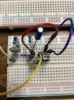
I took some time this evening to work on a jfet circuit. See below schematic. My general understanding is that the fet needs half the input voltage to work. The schematic calls for a 100k trim pot but I needed a 2m trimmer to get the input down to 4.5v. The sound is very splatty and doesn’t sound at all like it’s supposed to. The signal dies off almost immediately too. I tried with a j201 and now a 2n5457. The pinout in the pic is GSD read left to right. Can someone please help? There’s gotta be something stupid I’m missing. I took out the 68k resistor and put in a 100n coupling cap. The output cap is also 100n.

I took some time this evening to work on a jfet circuit. See below schematic. My general understanding is that the fet needs half the input voltage to work. The schematic calls for a 100k trim pot but I needed a 2m trimmer to get the input down to 4.5v. The sound is very splatty and doesn’t sound at all like it’s supposed to. The signal dies off almost immediately too. I tried with a j201 and now a 2n5457. The pinout in the pic is GSD read left to right. Can someone please help? There’s gotta be something stupid I’m missing. I took out the 68k resistor and put in a 100n coupling cap. The output cap is also 100n.