Interesting that you ask that. I don't think it's upside down. The numbers on it are matched up with the numbers on the main PCB. And the way I have it matches this photo from this previous successful build:
Another 2-in-1 from EffectsLayouts. This one is a TS10/Klon. For the Klon side I used old 1N34a diodes from stompboxparts.com. They measured a bit all over the place, but I did find two relatively close to the target Vf of .350V on my DCA55. Sounds great! The combination was obviously inspired...

forum.pedalpcb.com
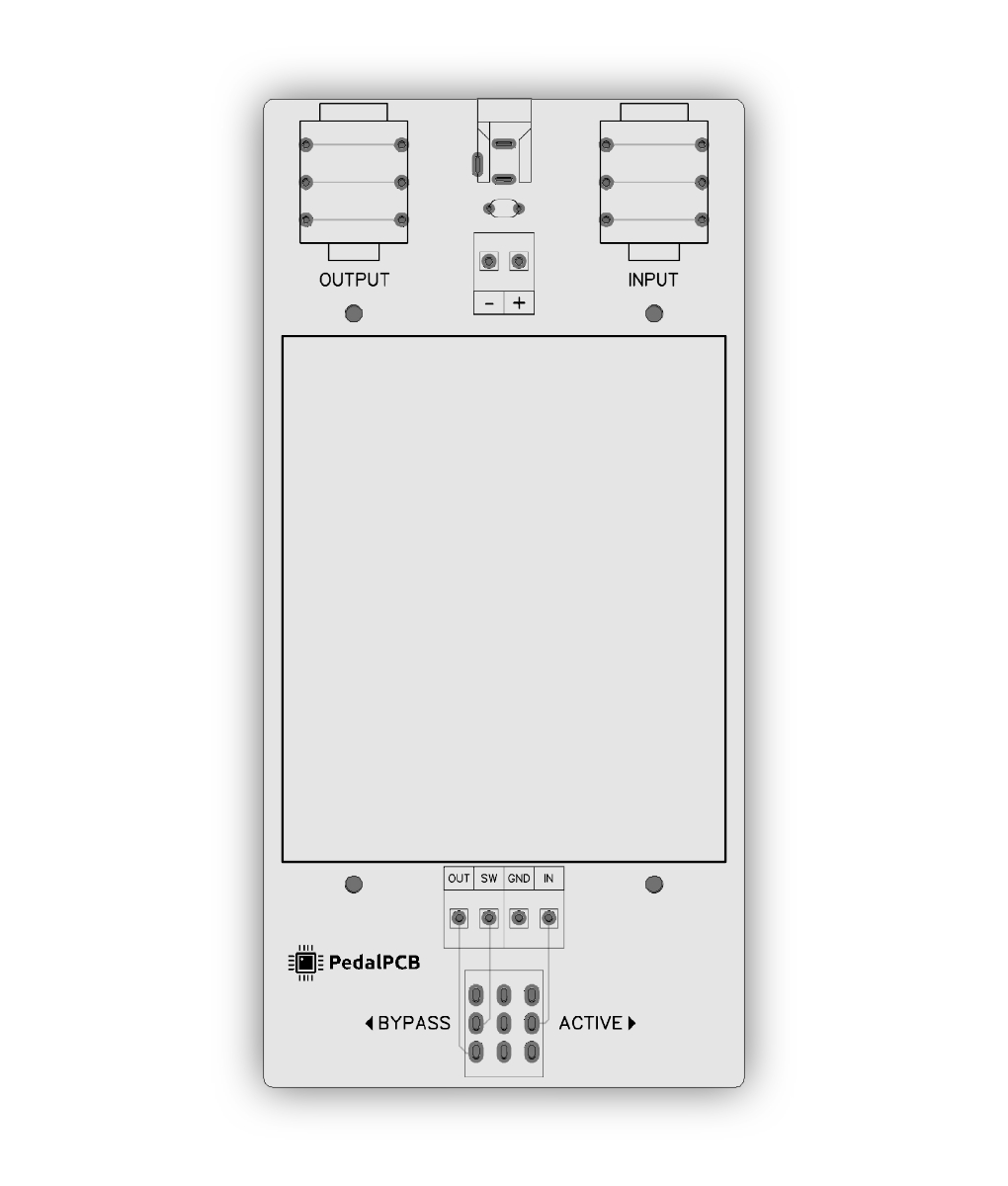
However, I did have it upside down first. So I solder sucked all the solder off, removed it and re-soldered it in the correct orientation. Is it possible one of the pads got messed up? The continuity for on and off are correct though. Also, these footswitch PCBs are a tight fit compared to the PedalPCB ones.