joelorigo
Well-known member
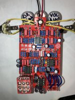
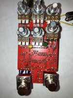
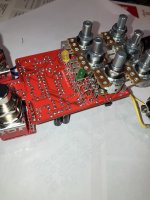
I have an Effects Layouts Kentauride that I have finished but there is so sound in either bypass or effects. This is the first time I've had this specific issue; could someone tell me what is the first thing to do? (Photos included)
Bellow are links to the project and the build doc.
Bellow are links to the project and the build doc.