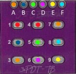
King Nothing Not Working

ninjagrips

New member
So I recently bought and built both a Diplomat and a King Nothing.

The Diplomat works great, but the King Nothing does not. I get a signal going through it when it’s not active, but if I stomp the switch, the sound cuts out and the LED doesn’t turn on.

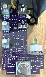
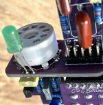
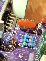
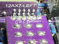
I can’t figure out what I’ve done wrong. I’m attaching a pic of the build.

I’ve tried two different tubes so far.

Can anyone help me diagnose what’s going on here? I would really appreciate it!
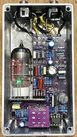
IMG_5490.jpeg

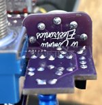
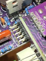
Edit: I may have screwed up the switch daughter board. I was trying to make sure none of the pads had solder connecting them and I stupidly scratched some of the mask off. I also swapped out the switch, thinking maybe there was something wrong with the first one.
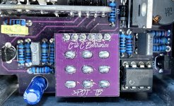
IMG_5503.jpeg
 
Last edited:
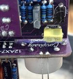
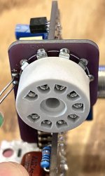
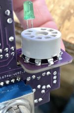
Scratched solder mask shouldn't be an issue, I wouldn't worry about that. Can we see a picture from an angle showing the solder connections of the tube daughter board? Also can you confirm this is a 12AX7 daughter board and that I didn't accidentally send you two EF86 boards? Also can you remind me what power supply you're using with it?

Nothing is really jumping out visually, so the next step would be to have you start checking voltages. I would recommend removing the tube when checking voltages just to remove any possible variables.

WHEN CHECKING VOLTAGES IN HIGH-VOLTAGE CIRCUITS EXTRA CARE IS REQUIRED. IT IS RECOMMENDED THAT YOU ONLY HAVE ONE HAND NEAR THE CIRCUIT AT A TIME AND THAT YOU KEEP THE OTHER HAND BEHIND YOUR BACK OR OTHERWISE AWAY FROM THE CIRCUIT.

I typically stick the negative probe of the voltmeter into one of the enclosure screw holes (making sure it sits at an angle so it makes contact at all times) and keeping my left hand behind my back while the right hand holds the positive probe to poke things.

For starters, there are two places I would recommend you check:
  1. V+ pad, should be close to 9VDC (typically lower due to diode drop, but will depend on your power supply)
  2. cathode pad of D2. This is the high voltage rail, it should be 230VDC or so.
 
I assume so, that’s what it says on the case, and I got it from AES…

Is there something I can do to check it?
 
I'm still hung up on the fact that your voltages look good but the LED isn't turning on. Have you checked continuity between the sets of terminals on the 3PDT? i.e. make sure that when switch is active, all the middle row pins connect to the bottom row pins, and when bypassed that the middle row pins connect to the top row pins. This can be done without power supplied.

The only other thing I can think of (which I haven't done yet) is to check every single component and make sure it's the correct value. Other than that typical things like checking for bridging and cold joints, particularly on the tube daughter board. A bad connection on the tube daughter board can ruin everything.
 
So with the pins on the switch, should ALL the middle row have continuity with ALL the bottom row, and same with the top row, when switched, or just the ones in line with each other?

I’m getting continuity with each pin in line vertically, but not necessarily say if I try the far left pin with the far right pin on the next row, if that makes sense.

Yeah I’m just not sure about the switch and its daughter board, but it’s the second switch I’ve tried.

I’ve looked over every connection and nothing looks wrong, all the tube board connections look good to me, and I’ve looked at all the parts to make sure they’re correct, but I haven’t tested their values, yet.

Should I try yet another tube, or should the LED come on even without a tube installed?

I did see the LED come on briefly while trying to check continuity between the switch daughter board connections, and where they lead to. I’m not sure if I accidentally connected something I wasn’t supposed to, or what.
Should have continuity with each pin in line vertically, not all of them across the row.

The LED should definitely be coming on even without the tube installed, so it sounds like there's a bad connection somewhere. I would recommend double checking and reflowing the solder connections on the tube daughter board and switch daughter board and see where that gets you.
 
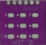
What footswitch pad number goes to the individual 6 pins for Continuity check?
3PDT Traces.jpg

3PDT switch pins:

Pedal bypassed:
  • 1 -> 2
  • 4 -> 5
  • 7 -> 8
Pedal active:
  • 3 -> 2
  • 6 -> 5
  • 9 -> 8
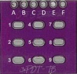
Looking at the top row where it connects to the main PCB:

Pedal bypassed:
  • A -> F
  • B -> C
  • No continuity on other top pins
Pedal active:
  • A -> B
  • C -> D
  • E -> F
Note that these connections are the same across all C2C projects using a 3PDT-TB board and all Sushi Box projects using a Sushi Switch-L board.
 
I’m not getting any continuity between pads C and D with the switch active.

With the switch bypassed, I don’t seem to be getting continuity between A-F or B-C.

I think all the numerical pads check out, though.
 
I’m not getting any continuity between pads C and D with the switch active.

With the switch bypassed, I don’t seem to be getting continuity between A-F or B-C.

I think all the numerical pads check out, though.
Pins C is ground and D is the LED cathode connection, and they correspond to switch pins 5 and 6 respectively.

Pin A is the input jack and F is the output jack. Pin B is the effect input.
 
First I would recommend checking continuity between Pad A and the input jack, as well as Pad F and the output jack, make sure those are what they're supposed to be.
 
So is this correct?
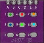
That means, your in bypass when 1 2, 4 5 & 7 8 are connected???
Which one is GROUND!

3PDT Desigmnation Dots.jpg
 
Last edited:
So is this correct?
That means, your in bypass when 1 2, 4 5 & 7 8 are connected???
Which one is GROUND!

View attachment 68680
That is correct, my only note would be that switch lugs 1 and 4 are permanently connected through a trace on the switch PCB so they should probably be the same color.

Pin C (switch lug 5) is the ground connection. When the pedal is bypassed, it shorts to the effect input (pad B, switch lug 2) through an internal trace between switch lugs 1 and 4. When the pedal is active, ground shorts to the LED cathode connection (pad D, switch lug 6).
 
Back
Top