KLICHE MINI not working

JBODRUMS

New member
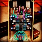
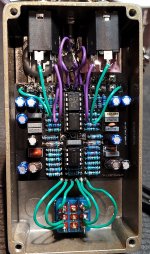
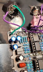
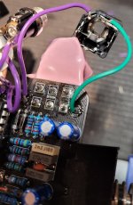
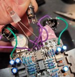
This is my first pedalpcb and I thought I had everything soldered up correctly. These 1/4in jacks I'm using have 5 lugs which is really confusing, but from looking inside them I feel like I have them wired up correctly. Also the dc jack I'm using might be wired up incorrectly. The problem I'm having is the thing won't turn on at all..so I'm thinking the dc jack is the culprit. If someone could help me out that'd be awesome! Thank you.
 

Attachments

  • 20210126_214154.jpg
    20210126_214154.jpg
    1,007.7 KB · Views: 56
  • 20210126_215930.jpg
    20210126_215930.jpg
    1.2 MB · Views: 52
  • 20210126_220002.jpg
    20210126_220002.jpg
    937 KB · Views: 44
  • 20210126_220115.jpg
    20210126_220115.jpg
    1.2 MB · Views: 51
I'm having a hard time seeing the insides of the jacks and I'm not familiar with them, but if you have a digital multi-meter you can test it for continuity to make sure you've got it wired up correctly (if you don't have one they are super helpful for all kinds of things). It also looks like you may have a different PCB for the Kliche Mini than the one that's currently up right now, which makes it a little tougher to see where everything goes. Are your GE diodes both facing the correct direction?

Edit to add: I need a strike-through option for test here, lol. I wasn't looking at the correct PCB when I made my comments. You can disregard everything after the DMM comment :)

Add'l edit: found the strike-through! I shouldn't try to be helpful after a rye or two lol
 
Last edited:
That metal DC jack isn't going to work unless you're using a plastic enclosure.... The outer sleeve of the DC power plug is positive and will be shorted to ground through the metal enclosure. You can test it out of the enclosure, but you'll need to replace that jack with a plastic type before installing it back into the enclosure.

Here's the proper pinout of the 1/4" jacks. You're looking for the Sleeve and Tip lugs (not Switched).


800px-1-4%22_Jack_Pinout.jpg
Coming up on this myself in a similar build - if I have a plastic, fully insulated power jack will I be able to safely use standard mono 1/4" I/O jacks?
 
Ok I'll have to check with my multimeter on the jacks. I have the new revision. I think the diodes are in the right direction from looking at the pcb.
 

Attachments

  • Screenshot_20210126-222838_Gallery.jpg
    Screenshot_20210126-222838_Gallery.jpg
    440.4 KB · Views: 3
That metal DC jack isn't going to work unless you're using a plastic enclosure.... The outer sleeve of the DC power plug is positive and will be shorted to ground through the metal enclosure. You can test it out of the enclosure, but you'll need to replace that jack with a plastic type before installing it back into the enclosure.

Here's the proper pinout of the 1/4" jacks. You're looking for the Sleeve and Tip lugs (not Switched).


800px-1-4%22_Jack_Pinout.jpg
Thank you so much! Sorry I'm very new to all this. So I guess I need a plastic dc jack now. I just gotta figure out which one will fit the same size hole I have in my enclosure.
 
Works after
Thank you so much! Sorry I'm very new to all this. So I guess I need a plastic dc jack now. I just gotta figure out which one will fit the same size hole I have in my enclosure.
Ok everything is working now except LED. I put it on a breadboard to see if the LED still works and it does. Am I missing something on the footswitch wiring or?
 
Back
Top