No Power/LED when Connecting Power to Pedal

snot_kid

New member
Hi team.

I'm not entirely sure what I'm doing wrong, but I've built the Blue Shoe Gai Pan into the enclosure, and the LED/pedal isn't powering up when the footswitch is engaged.

The DC jack is isolated, and the pedal is powering up when the 1/4" jack in/out aren't wired up to the enclosure, so I'm assuming it's a grounding problem? I am using metal 1/4" jacks.

There's no continuity between +ve and -ve power, so there doesn't appear to be a short, but it's acting in that way?

Very confused. I've built many other DIY pedal kits, and this is the first Im having problems with.

I'm assuming metal 1/4" jacks are fine, as loads of my other pedals use them with isolated DC jacks...

Please give me some help!

Thanks - Keria
 
It is almost impossible to help without seeing what you’re seeing. Please upload some clear pics of your build including both sides of the pcb and connections to jacks and footswitch.

Here’s my typical order of operations:

Step 1: close visual inspection. Are all connections correct? All component values correct? No cold or bridged solder joints? Proper orientation of polarized components? Using breakout boards properly?

Step 2: voltages and continuity

Step 3: audio probe

Please provide pics including both sides of the board. If you haven’t already reflowed all solder joints, you might want to. That often helps.
 
Hah sorry! I should have done this in the original post. I'll try and take some photos today. Was getting frustrated last night trying to figure things out. I realised the dual gang pot didn't have the plastic isolation (which I never saw originally) so I put some tape over that, but still no luck.

For now, the pedal is working 100% when the input and output jacks aren't mounted in the chassis (audio passing through, LED on, transistors at +9v, pots all work) but as soon as one of them is, no audio or LED light when the footswitch is engaged.

Hopefully I can get things to work by this weekend, as I have a gig I'm hoping to use this pedal on :L
 
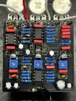
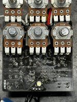
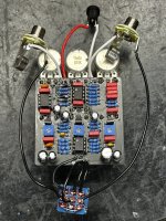
Here are the photos. Please ignore the black wire at the bottom that isn't soldered on. It came off last night as I was mounting and unmounting the PCB. The pedal was passing audio through the last time I tested it. I'm also out of IPA so my board is a bit fluxed up ._. Contact cleaner isn't working for me.

IMG_8443.JPG
IMG_8444.JPG

Not 100% sure what voltages I should check, but I what was curious is when I checked the +ve and -ve voltage from the DC jack to chassis ground, this is what I got:

+ve lead: ~+3.5v
-ve lead: ~+12.5v

I have no idea if that is normal or not, so I'm keen to hear what other people think.

Thanks - Keria
 
+ve lead: ~+3.5v
-ve lead: ~+12.5v

Something is very not right here. Your -ve lead should be connected directly to the case and so you should be getting 0v here. The +ve lead should then be reading about 9V
 
Hard to say but the transistor under the b10k pot of the bottom row looks to have solder bridge... I may be wrong.

How did you clean that board ?
 
Yea sorry, my lighting and the flux residue makes it a bit hard to see. Just checked now, and there is no continuity between any of the pins on each transistor.

I'm out of IPA, so I'm currently using contact cleaner, which isn't the best solution. Currently have some IPA on order.
 
  • Like
Reactions: Nic
Thanks for the extra photo. Your wiring looks right to me. If you’re using a trusted power supply, then like Nic suggests, I might start looking for a solder bridge somewhere. Real hard to tell from here what’s flux and what’s solder.
 
Just went through the components and checked values and bridging. Everything is looking good.

I've started tracing the signal path to confirm everything is ok there.
 
Thanks for the extra photo. Your wiring looks right to me. If you’re using a trusted power supply, then like Nic suggests, I might start looking for a solder bridge somewhere. Real hard to tell from here what’s flux and what’s solder.
Yea I'm using my Pedal Power 2 Plus which I haven't had any issues with so far (been using it for 8 years now).

Kinda stumped at this point. I have a few other builds I need to house, so I might try those and see how I do. Feeling a bit at a loss with this build :( It's the first pedal build I've had where I couldn't diagnose the problem.
 
Yea the pedal works fine when not housed in the enclosure. When everything minus the 1/4” jacks are housed, everything still works. As soon as 1x 1/4” jack is installed, no audio or LED light passed through.
Have you checked the 1/4” ground pads along with 9v + and - wiring? Any stray bits around those connections at top of board?
 
Yea, everything was hooked up fine without any shorts. Chassis had continuity to -ve terminal and 1/4" jacks had continuity to chassis ground and -ve terminal (1/4" jacks also contact to chassis as well, they're not isolated).
 
With power on, and the black lead of your multimeter on the - wire from the jack, and the red lead on the + wire from the jack what is the reading?
 
I know it doesn’t help with this issue but if you can adjust the temp of your soldering iron I would turn the heat down a bit. The board looks like it has been really hot in multiple places. If your not careful you could damage a part or even a trace. Black boards are the worst for showing solder splatter, heat etc but this one looks a little rough. I am pretty new to this forum but have built tons of pedals over the years so I apologize if this comes off as rude. You may want to get some vero boards and adjust the heat and practice. Not only will it make your builds better but it would also make it a little easier to see the joints to help trouble shoot. I speak from personal experience. I have cooked a few boards in my early days, lol.
 
Back
Top