SOLVED Marigold Fuzz Noise but no signal (bypass works)

grbrum

New member
Hello, this is the first pedalpcb board I build. I was having a lot of troubles with the wiring but this is now where I can't seem to advance further

bypass is working.
when on, led turns on (picture does not show LED because It is not soldered to the board)
when on, with volume at zero, there is no sound. as I increase the volume, there is only noise (no signal though).
Both Tone and Fuzz knobs affects the noise, so it seems there is no issue in that part of the signal path.

Actions taken - melted every solder to make sure no dry solder, checked components (hopefully didnt miss anything).

substitutions to the original design:
1N270 in place of CG92H
1N4732 in place of 4V7
GT402BC in place of OC140

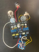
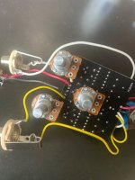
attached are some pictures, maybe someone can help and I will feel horrible if it is something ridiculous.
thank you all.
 

Attachments

  • IMG_9143.jpg
    IMG_9143.jpg
    435.3 KB · Views: 23
  • IMG_9144.jpg
    IMG_9144.jpg
    399.6 KB · Views: 23
Your soldering looks good and I’ll take your word on all the components being correct. Is the W20k pot insulated from the board?? Can seem to see a pot condom on it.

Also just make sure your subbed transistors have the same pin out compared to the original.
 
Your soldering looks good and I’ll take your word on all the components being correct. Is the W20k pot insulated from the board?? Can seem to see a pot condom on it.

Also just make sure your subbed transistors have the same pin out compared to the original.
The pot is not insulated but it is sitting high up not touching anything.
I could not find my info on the original transistors to compare.
I will review the components again to be sure. Maybe the color scheme are too close together or something.
Any comment about the wiring? I’m not too comfortable in this part.
 
Many of the Russian transistors pinouts are different, would concentrate there to start. Usually the base and collector are switched

Ag
 

Attachments

  • 6C3A48B8-5CCE-499C-BD6C-808666F84A5F.gif
    6C3A48B8-5CCE-499C-BD6C-808666F84A5F.gif
    42.8 KB · Views: 21
Many of the Russian transistors pinouts are different, would concentrate there to start. Usually the base and collector are switched

Ag
Dude. This is in Russian. Lol. Joking aside, I will research the original pins and see this item. Only worried because I did not leave much of the transistor pin left to switch them around 🤦🏻
 
  • Like
Reactions: fig
Just checked a oc140 on my dca55. It has the standard pinout C-B-E(marked), 402B is B-C-E

GT402V I have here emitters are NOT consistently marked or marked at all—could just be random crap on the transistor

Ag
 
Just checked a oc140 on my dca55. It has the standard pinout C-B-E(marked), 402B is B-C-E

GT402V I have here emitters are NOT consistently marked or marked at all—could just be random crap on the transistor

Ag
So if I understand this correctly I have to switch the position of b/c to fix the problem?
With the center pin facing away from you which is the emitter?
Thanks so much for this. I will post my findings
 
Isn't a OC140 an NPN and GT402B a PNP?
I read someone saying they are possible replacement. Your question went right above my head.
If what you are saying is the problem then it means I got the wrong substitution? I guess I need to do some more research on that. Thanks
 
  • Like
Reactions: fig
Look at the datasheet for each part number. PNPs and NPNs operate at reverse polarity from one another. It's not really about the part number, it's about the polarity, gain, and leakage measurements for the circuit you are building.

I looked at the build doc, and it calls for an NPN germanium.

@mdc gives the target values here

Good luck!
 
Last edited:
+1 for socketing transistors so it’s easy to audition them or take them out if it’s a problem. If you settle on a set you like you can then solder them into the socket or use some super glue.
 
Last edited:
  • Like
Reactions: fig
@fig Is correct OC140 is NPN
GT402V is PNP

The GT404 is NPN you sure it's a 402

Just for info an NPN requires a positive voltage on the collector for current to flow between collector and emitter a PNP requires positive voltage on the emitter for current to flow between the emitter and collector

So your transistor won't be conducting correctly
Hello. It is a 402. Would the GT404B be a reasonable replacement instead?
They are available at small bear


Product Description​

NPN complement of the GT402B Take note of the pinout! Gain range of 80 to 140, some fairly leaky as NPN germanium often is, but still usable in BMPs, Fuzzrites, etc.
 
I color coded white for input and yellow for out.
No I meant actually plugging into the effect. Keep in mind if the components are facing you the pedal is upside down. Guitar going into the white (left based on pic) jack. The alternative is you have a short or a bad component somewhere on the board
 
  • Like
Reactions: fig
Back
Top