You are using an out of date browser. It may not display this or other websites correctly.
You should upgrade or use an alternative browser.
You should upgrade or use an alternative browser.
Missing Build Docs / Schematics
- Thread starter Robert
- Start date
Robert
Reverse Engineer
Any chance on getting the microblend schematic? Want an active blend but not set up for SMD so would like to Vero it

Robert
Reverse Engineer
Q3's collector voltage is -9v?!
Yep, (Re)Confirmed.
anevilspar7an
Well-known member
May I have the schematic for the 3PDT Breakout Board with Output Boost Robert?
Robert
Reverse Engineer
May I have the schematic for the 3PDT Breakout Board with Output Boost Robert?

Wizardofwoz66
Active member
Any chance I could get the OG Synchrowah schematic? I've had the board for a few years and finally built it and I have no LEDs working at all, including the one for the LFO, so I need to start chasing voltages lol
balazs.bencs
Member
Hey Robert,
Any chance you could upload the build docs/schematics for Acrobat?
I contacted Musikding, to see if I can buy the kit from them (I am in the EU), but they can only sell it if the build docs are online.
Thanks a lot!
Any chance you could upload the build docs/schematics for Acrobat?
I contacted Musikding, to see if I can buy the kit from them (I am in the EU), but they can only sell it if the build docs are online.
Thanks a lot!
Feral Feline
Well-known member
Tutorials
Acrobat Users
https://acrobatusers.com › tutorials
The Adobe Acrobat User Community is a global resource for users of Acrobat and PDF, with free eseminars, tips, tutorials, videos and discussion forums.
DGWVI
Well-known member
Bumping this
And requesting the doc for the Oroideous
Hey Robert,
Any chance you could upload the build docs/schematics for Acrobat?
And requesting the doc for the Oroideous
Robert
Reverse Engineer
y-u-no-f800b
Member
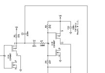
For being such a simple chip, it's soooo hard to represent the 4007 in a schematic. The most beautiful I've seen is the original MPF-1 schematic, but even that is unwieldy.

My lifehack is to use symbols for discreet mosfets and NOT gates, depending on how the 4007 is configured in circuit, and tack the appropriate pin numbers on the schematic

Thanks for the schem! Now I know why that B10kDG does what it does. Mods ahoy!
I do 'em like this, that about the same as your method?For being such a simple chip, it's soooo hard to represent the 4007 in a schematic. The most beautiful I've seen is the original MPF-1 schematic, but even that is unwieldy.
View attachment 112539
My lifehack is to use symbols for discreet mosfets and NOT gates, depending on how the 4007 is configured in circuit, and tack the appropriate pin numbers on the schematic
Thanks for the schem! Now I know why that B10kDG does what it does. Mods ahoy!
But uhh... that Stonedeaf schematic is... well it's certainly an interesting approach.
Edit: Just realised this read like I was complaining about Rob's CD4007 drawing, was referring to Stone Deaf's approach to the MPF-1!
Attachments
Last edited:
drgonzo1969
Well-known member
Is there a drill template for the USB Pedal Power Converter?
If you like how that one turned out, I could share it.Is there a drill template for the USB Pedal Power Converter?
Thread 'A powerful trio' https://forum.pedalpcb.com/threads/a-powerful-trio.21563/
Edit : you can now find it here
1590A Thread 'USB Power'
Here is the drill template I used for mine. Fell free to use.
Robert told me that if you use a 5mm Male standoff paired with a 20mm Female standoff (on opposite sides of the PCB) you don't need any mounting holes or hardware on the outside of the enclosure.
Robert told me that if you use a 5mm Male standoff paired with a 20mm Female standoff (on opposite sides of the PCB) you don't need any mounting holes or hardware on the outside of the enclosure.
- Nic
- Replies: 0
- Forum: Tayda Electronics Drill Templates

Last edited:
MichaelW
Well-known member
Bumping this
And requesting the doc for the Oroideous

Bypass wiring like this....

drgonzo1969
Well-known member
Most Excellent! Thank good sir.If you like how that one turned out, I could share it.
Thread 'A powerful trio' https://forum.pedalpcb.com/threads/a-powerful-trio.21563/
Edit : you can now find it here
1590A Thread 'USB Power'
Here is the drill template I used for mine. Fell free to use.
Robert told me that if you use a 5mm Male standoff paired with a 20mm Female standoff (on opposite sides of the PCB) you don't need any mounting holes or hardware on the outside of the enclosure.
- Nic
- Replies: 0
- Forum: Tayda Electronics Drill Templates
fydo
Well-known member
Not sure if this is the right thread, but I've noticed on several build docs that the switch position labels are missing. For example, the Pastel Preamp has two double throw switches, one engages the Hi-Pass filter, and the other presumably switches between 720hz and 400hz as the frequency for the low-pass filter, but the documentation doesn't show which is which.
Another example is the Equilux and Equilux Mini. The three rotary switches each have four positions that correspond to specific frequencies.
It might seem a little pedantic but even on something like the Skeptical Buffer it would be good to know which direction of each switch is the "on" position.
I really liked seeing the switch position documentation on the XC Phase. It was very helpful when laying out the labels / design! As a software developer by day, I tend to view the enclosure design as a small fun exercise in building a UI that is both pleasing to look at, and (more importantly) is clear as to what the pedal does / is doing. Having clear documentation makes for a much more enjoyable experience")
Another example is the Equilux and Equilux Mini. The three rotary switches each have four positions that correspond to specific frequencies.
It might seem a little pedantic but even on something like the Skeptical Buffer it would be good to know which direction of each switch is the "on" position.
I really liked seeing the switch position documentation on the XC Phase. It was very helpful when laying out the labels / design! As a software developer by day, I tend to view the enclosure design as a small fun exercise in building a UI that is both pleasing to look at, and (more importantly) is clear as to what the pedal does / is doing. Having clear documentation makes for a much more enjoyable experience