SOLVED Popping noise - rotary switch Rangemaster

8 way rotary switch on my Rangemaster makes loud popping sounds sometimes when rotating the dial. Is this a defective unit or is there a way to fix this?
 
Not really, but it pops much worse the first time I turn the knob. If I turn the knob through the positions, it happens the first go around but then it doesn't happen (as loudly) when I go through the positions again. Also seems to happen more when I'm rotating CW.
 
Try clicking the 3PDT on and off a few times, then try the rotary to see if it still does it

It could be a few things internal or external something as simple as a dry solder joint, leaky cap or your power supply etc

Measure for DC on the in and out jacks:

From Geofex


. Fortunately, you can use a DVM to measure the DC on the signal lines and figure out whether it's the stompbox itself or something outside that's causing this to happen. Just measure the DC voltage between the tip and ring of a cord plugged into the input and output of the stompbox with the effect NOT bypassed. If the stompbox has an internal problem like a leaky coupling cap, there will be DC. If there's no measurable DC voltage, the popping is something outside the stompbox.
 
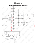
It pops due to a design overlook. Take a look at the schematic. Unselected caps have one leg up in the air, free to build up charge and then pop when you discharge them to ground through the guitar pickups by selecting them. Try adding 10 Meg pull-down resistors as shown below. Alternatively, you can get rid of R1 and make the red resistors 1Meg.

BTW, I doubt there's much audible difference between switch positions 6, 7 and 8.

rf.png
 
Last edited:
It pops due to a design overlook. Take a look at the schematic. Unselected caps have one leg up in the air, free to build up charge and then pop when you discharge them to ground through the guitar pickups by selecting them. Try adding 10 Meg pull-down resistors as shown below. Alternatively, you can get rid of R1 and make the red resistors 1Meg.

BTW, I doubt there's much audible difference between switch positions 6, 7 and 8.

View attachment 73833
Thanks, this looks like the answer!

Any tips on adding these to the board?
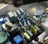
 
I guess the easiest way migh be to put them on the solder side, between pins 1-8 of the switch and ground. Maybe arrange them like the spokes of a wheel, meeting in the middle and going to the ground together. There might already be some grounded copper extending behind the switch. If this is the case, just scrape off some solder mask and you have a central ground pad.
 
Worked great! I suppose this could have been done with a single resistor, but I dig the tepee thing.

I hope @Robert implements this change in future versions. This makes the pedal much more enjoyable to use. The popping was pretty loud and annoying previously.

Thank you kindly, @JTEX.

edit: much much better after this mod. There is still a tiny pop, like with any switch, but the pedal is now overall very quiet and usable

Screenshot 2024-04-25 at 5.33.58 PM.jpg
 
At higher frequencies all 8 of them are directly in parallel with each other and with R1, so I picked a value high enough that it doesn't affect the input impedance too much even when paralleled 8 ways. 10Megs is one of the highest widely available values.
 
Last edited:
You could say the same thing with toggle switches with Gain options and Clipping options, they Bang & Pop!
All the boutique pedals??? do the same thing!
Most people accept it or turn the pedal to bypass & switch then turn the pedal back on.
I would have done that on the bottom side so it doesn't look so invasive!!!
 
At higher frequencies all 8 of them are directly in parallel with each other and with R1, so I picked a value high enough that it doesn't affect the input impedance too much even when paralleled 8 ways. 10Megs is one of the highest widely available values.

Ah, that makes sense.
 
Back
Top