Problems with Caesar chorus

Jkhicks

New member
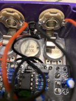
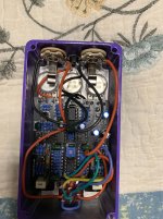
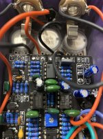
I just finished the Caesar chorus only to find that Im not getting power through the jack. I can plug a 9v battery to the pedal and it gets hot to the touch. Take the jack out hook it to a 9v power source and it will turn on an unwired LED. With the jack in the pedal and the unwired LED touching the posi and negative jack post
,I get nothing. Any help appreciated
 
finally. Lol
 

Attachments

  • IMG_1737-compressed.JPG
    IMG_1737-compressed.JPG
    223.6 KB · Views: 49
  • IMG_1738-compressed.JPG
    IMG_1738-compressed.JPG
    410.6 KB · Views: 48
  • IMG_1741-compressed.JPG
    IMG_1741-compressed.JPG
    293.1 KB · Views: 45
If the 9 volt gets hot when you plug it in to the pedal DC input, that means that your circuit is pulling *a lot* of current.

I would measure the resistance between positive and negative on your pedal. I'd bet you'll read close to 0 ohms. If that's the case, I would start looking at the ground and positive connections to your PCB, to the left of your depth pot. I wouldn't be surprised if you've got a solder bridge or a whisker from your hookup wire creating a short circuit across your power supply.

Also - I noticed you haven't populated the LEDs in the LFO shape circuit. Without these, your triangle LFO shape won't work.
I blew up the picture above to look for that. I can’t see a bridge. Is it possible I have a bad pcb?
 
I blew up the picture above to look for that. I can’t see a bridge. Is it possible I have a bad pcb?

The bridge could be on the back, not visible form the photos.

A bad PCB isn't impossible of course, but not the most likely cause of this sort of problem.


See this little sliver of a wire strand right here?
1642648449189.png

If you have one of those right here (on the back side, they usually occur on the side the wire is entering the PCB) it could cause the problem you're having.
1642648555698.png


You'll have to pull the PCB out of the enclosure to check. Post pics when you do, and go ahead and install those two LEDs while you're at it.
 
Last edited by a moderator:
There was a stray on the back side. I’m getting 9v to the board,but not through the 9V1 zener. I’ve ordered the leds and a new zener. Also no power to the switch. I hope it’s the zener…edit. I just misssed the leds. I guess I thought those were just power indicators as usual.
 
Voltage isn't supposed to pass through the 9V1 zener, it goes to ground.

It's purpose is to hold the voltage at 9.1V. You should measure around 9V on one end, but no voltage on the other.
 
Take a deep breath - you'll be fine. Think of this as a learning opportunity.

Potentially uncomfortable truth: You probably either made a mistake, or you have a bad solder joint somewhere. It's not a big deal. Even experienced pedal builders fuck up from time to time, especially when taking on a new circuit. It's normal, it's part of the process.

It's extremely unlikely that you have a bad Zener. MAYBE there's a bad component in the mix, but it's far more likely that there's simply a problem with the build that you're not aware of yet. Double check all your component values. Inspect the board for solder bridges or whiskers. Figure out where the problem is before you go changing out components - trust me, de-soldering is time consuming, has plenty of potential to rip out a trace or two, and more often than not won't lead to the desired result.

Find, then fix. The other way around will lead to frustration and a pedal-shaped hole in your wall, if you're like me.

The good news is that you can continue troubleshooting without the red LEDs for the triangle wave LFO. Just know that the shape switch won't do anything until you get those red LEDs installed.
 
I’m getting power through the board except where you feed the switch. The board is completely dead there. I’ve disassembled the pedal and there are no bridges. Reflown some suspicious joints.
 
Have you double checked all component values? It's tedious, but going through resistor-by-resistor and cap-by-cap could lead you to something that is incorrectly placed.

Another step that could help us diagnose what's happening here: take your voltage to ground across all IC pins. They're numbered like so:

1. 8
2. 7
3. 6
4. 5

Post those measurements for all 4 ICs. That may help us pinpoint the problem

Another question: does your LFO LED light up and pulse when you plug the pedal in? If not, that's an indication that your LFO is not operational, in which case no signal will pass through your MN3207. This should light up regardless of if the pedal is "on" or "off".
 
Back
Top Bottom