Procrastinator refuses to work.............. (2nd time already)

Ariosto

Member
Hello there,
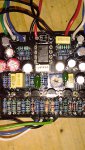
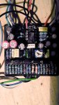
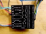
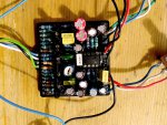
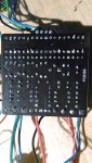
Some months ago I bought one Procrastinator PCB from Germany. Assembled everything and nothing happened. As the unsoldering job is sometimes expensive as buying one new, I purchased again the PCB. Checked every component before soldering, ready and............ Nothing. The audio signal go well when the effect is off (which makes me think that the wiring is OK), but no sound when engaged - I recorded a bit in my DAW and when I normalized the audio take it could be heard distorted signal. That could be a good sign maybe-.
I don´t have no much experience with audio probes, maybe someone here could give me some advice. I checked for cold joints but apparently is none. I suspect there could be a false contact in the transistor´s sockets, but honestly I am clueless.

Thanks in advance and hope to read from you soon!

Ariosto

PS: Sorry for the poor quality photos. If needed, I could make some more in the next days.
 

Attachments

  • 03.jpg
    03.jpg
    579 KB · Views: 25
  • 02.jpg
    02.jpg
    552.9 KB · Views: 24
  • 04.jpg
    04.jpg
    601 KB · Views: 17
  • 05.jpg
    05.jpg
    731.3 KB · Views: 20
  • 01.jpg
    01.jpg
    480.9 KB · Views: 18
Last edited:
Sorry I was a bit busy, but I took note of the voltages in the PCB:

IC:

1: 0.12 5: 0.12
2: 3.02 6: 4.43
3: 3.59 7: 7.17
4: 0 8: 0

TRANSISTORS:
C B E
Q1(BC549B): 8.90 2.77 3.36
Q2(K30A Y3E): 0.07 0.03 0.07
Q3(BC549B): 8.90 3.96 6.37
Q4(BC549B): 5.85 2.80 3.06
Q5(BC549B): 0.07 0.01 0.01
Q6(BC549B): 0.07 0.03 0.01

I feel like a noobie (and I am really, although I build many pedals), so I hope somebody could help me with this information. THANKS!
 
I suggest you take a look at the very low voltages you are seeing on three of your transistors -- Q3, Q5 and Q6. Those should probably be much closer to the voltages you are seeing on the other transistors. You should check to see if the electrolytic caps are placed correctly on the board for C4, C13, and C14, and also make sure you have continuity on parts that go from VCC to each of those transistors (use the circuit diagram in the build docs and your DMM to make sure all of those parts are properly connected to the PCB.
 
I suggest you take a look at the very low voltages you are seeing on three of your transistors -- Q3, Q5 and Q6. Those should probably be much closer to the voltages you are seeing on the other transistors. You should check to see if the electrolytic caps are placed correctly on the board for C4, C13, and C14, and also make sure you have continuity on parts that go from VCC to each of those transistors (use the circuit diagram in the build docs and your DMM to make sure all of those parts are properly connected to the PCB.
Hi and thanks for your reply!

Well, I already checked the position of the electrolytic caps and everything is OK with that -even the values are correct 1uf each (need to know if they work properly). I measured the voltages of the transistors NOT in the PCB, but in the legs of them. Then I can assume that they are properly connected... Now I must check the continuity on parts that go from VCC to each of those transistors as you say, but I still don´t have idea how to do that.

Keep you informed as long as I make any progress with the debug.

Ariosto
 
For this project and all the projects that follow, you will need to know enough about the circuit diagram to understand how it shows what parts on a circuit board should be connected to each other.

It also helps if you can generally understand the path that the audio signal takes through the board, the path the power takes through the board, and the parts of the board that are supposed to connect to ground.

You can use google search to find some articles about understanding electronic circuits and how to use your DMM to test the connections between the parts. For starters, do a search on "how to read a circuit diagram"
 
Back
Top