Reversed power?

JimmyS2

New member
Good afternoon folks, ive found myself in the troubleshooting forum.

My first thread here was about sourcing components as I am totally new to this, and several of you where extremely helpful. Now however, I've finally made my way through my first build and... nothin.

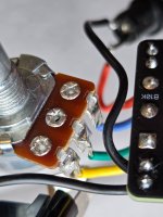
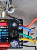
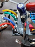
I did pretty much expect this, I can't imagine too many people fire up their first build first try, so fair enough. I built the amentum boost, figuring it looked simple, and then chose to stuff it into a 1590a, so it ended up being less simple. Truthfully I spent some time staring at all the stuff I needed to fit into the little box wondering if it was going to be a mistake, im sure its going to make troubleshooting and fixing a lot of fun.

20251230_140443.jpg

Upon hooking it up, no power. Then I noticed if I touch the end of a power cable to the sleeve (I guess?) The very end of the power jack, the led comes on. Bypassed, the signal seems to go through fine. When the pedal is engaged, signal drops, sounds thin and fuzzy, and of course this is while I touch the power cable just so, otherwise nothing.

Seems like the power jack is backwards, though I triple checked and I dont think so. Unless I dont understand something correctly, which is likely.

If anyone is confident I need to reverse the wiring to the power jack, I would appreciate a quick explenation, just so I can learn what happened. If I need to post some pictures of different angles I easily can, let me know.
 
The longer lug should be the positive lug assuming your power supply is a standard negative tip pedal power supply.

If you have a DMM a quick voltage measurement across the DC jack lugs will tell you if the polarity is correct.
 
Also, insulate your PCB with something more substantial than electrical tape.

Component leads tend to poke through and short to the enclosure... it's not always visible.
 
Well, the longer (sleeve) lug is connected to positive on the board. I'm sure this is elementary stuff, but my power supply shows tip negative like I would expect 20251230_155644.jpg

But the cables have the opposite shown. 20251230_155700.jpg

I dont know if that symbol on the cable makes any difference at all, or exactly what's backward here. In regard to insulating the board, will do! Hopefully I have room, its tight in there!
 
Ok, measuring at the cable shows about -9v, so tip negative I think. It seems I have power when the sleeve of the cable touches the sleeve of the jack, but not when plugged in. 20251230_162225.jpg

Perhaps I dont u derstand still, or perhaps the jack is faulty? I hesitate to blame the parts haha
 
So, I've ruled out reversed power I believe, I can measure about 9v between the sleeve lug of the power jack and any number of ground points. The diode is not reversed, as far as I can tell all of the wiring is in fact correct. Could I have just burned something in soldering?

Ive removed it from the case, and reattached the power jack so I could test. It is exactly the same so I guess I can rule out something shorting to the case. Ive confirmed polarity of the diode, led, and electrolytic cap, not sure how to check the transistor. As far as I can tell the wiring all seems correct, I was hoping something would eventually jump out at me.
 
Last edited:
Take it out of the case again and post close up photos of both sides of the board. Sharp eyed people amaze me with their ability find the cold solder joints…

Yes, as you surmise, this is a rite of passage.

I wonder if that cable you showed the closeup of is a reverse cable. I’m used to those being color coded. Most supply kits come with one, for those pedals like some fuzzes that are “reverse” wired.
 
20260102_124108.jpg 20260102_124136.jpg

Hopefully these are fairly clear. It looks so much dirtier this close up, I had no idea!

I wonder if that cable you showed the closeup of is a reverse cable. I’m used to those being color coded. Most supply kits come with one, for those pedals like some fuzzes that are “reverse” wired.

I checked out my power supply more closely, its an ehx S8, it came with 8 individual cords, one for each outlet, all the same. They all curiously show the tip positive marking, while the power supply itself shows the opposite.
 

Attachments

  • 20260102_124340.jpg
    20260102_124340.jpg
    301.1 KB · Views: 8
  • 20260102_124323.jpg
    20260102_124323.jpg
    364.4 KB · Views: 9
  • 20260102_124257.jpg
    20260102_124257.jpg
    325.8 KB · Views: 9
  • 20260102_124204.jpg
    20260102_124204.jpg
    358.3 KB · Views: 7
The S8 manual mentions the polarity conversion cable, but it's a female-male, while the normal cables are male-male. So I assume that shouldn't be the case here - but they are marked center negative unlike yours.

s8_manual.png

You could probably measure the cable end to end, sleeve-to-sleeve and tip-to-tip to check that they are normal and not polarity reversing? I'd advocate for such a simple test over checking which way you get 9V and which way is -9V because it's easy to make a mistake there.
 
Interesting. Measuring the cables tip to tip and sleeve to sleeve, they are not polarity reversing. They're all the female to female cables, so that's exactly what they should be. Not sure why they seem to have the wrong symbol molded into the plastic but it seems like I can safely ignore that, they should be delivering exactly whatever the power supply is providing.
 
this has got to be something obviously simple.... Are you 100% confident you are checking your polarity correctly with the multimeter at the end of your power cables after your power supply? black lead placed inside of power cable and red lead touching the outside sleeve of the power cable to double check the polarity that will be plugging into power jack? multimeter set to DC volts in at least 20V range... Should show a positive 9 volts or a little more. not -9 volts...
Past that my assumptions are:
Transistor got too hot when soldering
Footswitch soldering could be janky under the breakout board.. Which is exactly why I don't prefer them... If you overfill the pads solder can flow and possibly make contact with other solder blobs you filled on other pads.. If I use a breakout board I rarely fill the hole with solder...It's bit me a few times... Not too much else that could be wrong other than a component value waaay out of spec.
 
Thanks guys.

I re confirmed the power cables are providing the correct polarity, replaced the power jack with a new one, no change. So I pulled the transistor (might have toasted a pad or two getting it out, hopefully not) and checked it out with a meter, looks to be all good.

I suppose what's left is the switch, which is what I was hoping to avoid. I suppose I could just pull it and wire up a fresh one with no breakout board, I had kinda hoped the breakout board would simplify something I was a little intimidated by, but perhaps that's not the way.

I do want to at least confirm what went wrong before starting a new one so I dont repeat the mistake, the other ones I'm prepared to build are not this simple.
 
Back
Top