
Redspacecadet74
Active member
Hi, I’m hoping for some help troubleshooting the Special OD I just built.
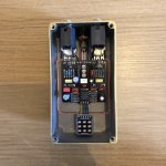
When I first plugged in the pedal I got no sound at all with the pedal switched on or off and the LED didn’t work either. I did a quick check and realised I had the positive wire from the PCB connected to the battery terminal of the power socket instead of the positive terminal. I quickly fixed this and plugged the pedal back in but still no sound or LED. So I did a more thorough check and this time I noticed that capacitor C13 is reversed, i.e. the positive lead is wired to the negative pad on the PCB and vice versa. Other than that everything looks correct to me (the photo below was taken before I retired the power socket).
Before I replace capacitor C13, I was hoping someone with more knowledge of circuit design could tell me if this explains why I’m getting no sound and/or why the LED is not coming on?
Attachments
Last edited:

")