Spirit Box Help!! Weird octave fuzz sound???

Itsjackbove

New member
Hey guys! First build using a belton brick and I thought i had it covered :(
I used some free wiring to give the finished product a look that I would aesthetically enjoy more than the classic 3-knob (no hate tho, just my preference) but idk if that’s the problem here. When I plugged it to test it out, it sounded nothing like a spirit box! It gave this really weird octave, sagged fuzz (sounds so cool) so maybe it’s a transistor problem?? I’ve built some pt2399 models before so I thought I’d give this a shot but I’m also relatively new to this. Any/all help is appreciated cuz I have no clue where to start looking for problems 🤷‍♂️
 

Attachments

  • IMG_9032.jpeg
    IMG_9032.jpeg
    557.5 KB · Views: 15
  • IMG_9032.jpeg
    IMG_9032.jpeg
    557.5 KB · Views: 15
  • IMG_9034.jpeg
    IMG_9034.jpeg
    499.7 KB · Views: 16
Your images are out of focus it's very difficult to see anything clearly

If you haven't already check all component values and orientation are correct as I say I can't see your resistor colour bands etc to check

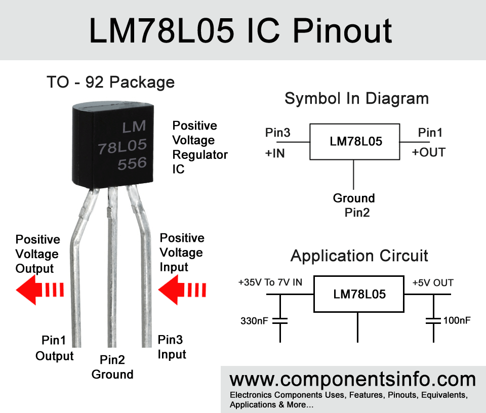
The transistors are 5v voltage regulators check to see you get 5v ish on the regulator output pins ICs 3 and 6 and 4.5v ish on IC4.1 pin 1
Here’s some better pictures :)
How would I go about checking the voltage on the transistors?
 

Attachments

  • IMG_9053.jpeg
    IMG_9053.jpeg
    570.2 KB · Views: 18
  • IMG_9054.jpeg
    IMG_9054.jpeg
    467.4 KB · Views: 18
Is the board touching that bottom potentiometer? If you don't have any cap, I would suggest you use the one on the top pot for that one.
my first thought too. the back of the PCB isn't touching anything; nor is the belton brick. im pretty sure it has something to do with the transistors (maybe??). trying to get one of the big shot users on here who has a masters in electrical engineering to help me out
 
L78L05-Pinout.jpg

Check pin 1 for 5v DC output. Stick negative probe in a screw hole on the enclosure and carefully probe pin 1. If you have clip on probes, this would be a good opportunity to use one. Be careful not to short pin 1 to pin 3.
There are a lot of opportunities in your wiring for problems. The uninsulated wiring of the footswitch is just, sorry, but bad. If the nut ever comes loose and the footswitch gets twisted, it'll be game over.
What gauge wire are you trying to use? 18-20awg? I'd advise getting some 24awg, at largest. 22 will work but can be tight. Anything over 24 is tough to use.
Your soldering skills are still developing, judging from the tope side. Very little is flowing through the pads. I'm going to suspect you have some cold solder joints, without seeing the bottom side. I would highly suggest socketing your ICs at least until your soldering skills are leveled up. It takes time a practice (and good technique). ICs are more sensitive to prolonged heating than other passive components. Sockets are very cheap insurance.
When you say "octave fuzz" sound, could you be more specific? Is there any effected sound or is it just fuzzy noise? Do the pots react to being turned?
I'll suggest reflowing the board, but take care with the ICs, and maybe even skip them at first. If you do reflow them, take your time. Do one leg, and pause of work other components for 15-20 seconds before doing another. Post some photos of the underside while you're in it. You should see solder flowing through the pad to at least being flush with the top side of the board. It's not necessary for it to flow through to the top, it's not even necessary, electrically, for it to flow through at all BUT it flowing through indicates that the pad and part were properly heated enough to make a good connection. It shouldn't take more than 3-3.5 seconds for it to do so. If it does, need to look at your solder or iron temperature. Adding a bit of flux when reflowing can help. MG Chemicals makes liquid flux pens that are great for this. Also, always clean your boards *before* populating. Oils from fingers etc are detrimental to good solder adhesion.
Hope this helps.
Oh. I'd consider rewiring the footswitch with insulated wire, for longevity sake.
 
Last edited:
The regulator pins left to right are output (5v) middle ground and power (9v)

Or you could check what voltage you get on the brick pin 1 and IC5 pin 1 which should be 5v ish


Checking those voltages mentioned will just let you know the power supply circuit is OK and your op amps aren't mis biased

Are you getting any reverb effect because the brick joints look like they need reflowing

All your resistor values look correct
 
L78L05-Pinout.jpg

Check pin 1 for 5v DC output. Stick negative probe in a screw hole on the enclosure and carefully probe pin 1. If you have clip on probes, this would be a good opportunity to use one. Be careful not to short pin 1 to pin 3.
There are a lot of opportunities in your wiring for problems. The uninsulated wiring of the footswitch is just, sorry, but bad. If the nut ever comes loose and the footswitch gets twisted, it'll be game over.
What gauge wire are you trying to use? 18-20awg? I'd advise getting some 24awg, at largest. 22 will work but can be tight. Anything over 24 is tough to use.
Your soldering skills are still developing, judging from the tope side. Very little is flowing through the pads. I'm going to suspect you have some cold solder joints, without seeing the bottom side. I would highly suggest socketing your ICs at least until your soldering skills are leveled up. It takes time a practice (and good technique). ICs are more sensitive to prolonged heating than other passive components. Sockets are very cheap insurance.
When you say "octave fuzz" sound, could you be more specific? Is there any effected sound or is it just fuzzy noise? Do the pots react to being turned?
im using 22 awg (stranded) and no, the pots are not reacting. its almost like a blue box or something. pretty weird sound. how would i check for the 5v DC output? also i usually only use the uninsulated to the ftsw just for a quick test and then I go back and "gig-proof" all of the little things. Its a quick solution but NOT at all long term. I appreciate the criticism :)
 
im using 22 awg (stranded) and no, the pots are not reacting. its almost like a blue box or something. pretty weird sound. how would i check for the 5v DC output? also i usually only use the uninsulated to the ftsw just for a quick test and then I go back and "gig-proof" all of the little things. Its a quick solution but NOT at all long term. I appreciate the criticism :)
Added to previous post.
Checking DC is outlined twice above.
 
They're not transistors. They're voltage regulators in a TO-92-3 package. Cereal comes in a box but not every box is cereal.
They convert the 9vdc to 5vdc. Where to order from is up to you. Amazon could be hit or miss. Check the ratings of the item and seller.
 
UPDATE: i used my brothers multimeter and i was reading 5v on all of the Pin 1's and 4.5-4.9 on pin 1 of the TL072's. Could it be from the electrolytic caps? all of the resistors have the correct values (as do the film caps) so im not sure what to check next...

any suggestions?
 
Back
Top