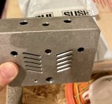
Here's my almost finished pedal. I just spent an hour with it. WOWZA! (I'll share some more detailed impressions when I do a build report
")
)
The knobs I bought are too big.
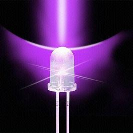
Another question though. This is the LEDs I have in there:
Get It Fast - Same Day Shipping

www.taydaelectronics.com
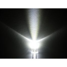
I wanted purple but they don't light up the inside very much. Would another one be brighter? Like this one maybe?
Get It Fast - Same Day Shipping
www.taydaelectronics.com
Or replace the correct resistor with a different value?