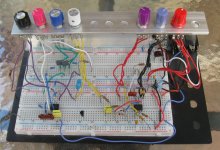
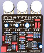
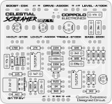
It might help to reduce noise & hum pickup, but mainly it's to make things a little neater.
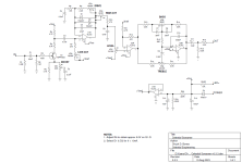
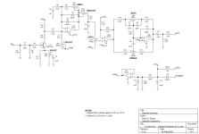
Here's the working schematic. I think it's pretty much done. I
might tweak a few component values. Q1 is a (mostly) clean boost. At low to medium BOOST settings, the freq response is flat. At higher BOOST settings the bass is rolled off and it acts like a mid-boost. High BOOST setting will produce some mild distortion. I chose MPF4393 because it has high gain at the desired drain current. You can try other JFETs, but you probably won't get as much boost. R4 & R5 ensure that U1A cannot be driven into hard clipping. C3, R7 & VR2 form a variable high-pass filter (LO-CUT). U1A and surrounding components are a typical TS soft clipping stage. C4 & R8 roll-off the bass below 48Hz. I was surprised to find that the 1N4148s I was using for clipping diodes were limiting the gain because of their leakage. We don't expect Si diodes to be leaky, but when DRIVE is dimed, even a small amount of leakage can reduce the gain a bit. I measured various diodes from my stash and found that the 1N400x diodes had some of the lowest leakage numbers. Even so, I picked the lowest leakage diodes from the bunch. You can use any 1N400x diodes, just measure them with a DCA75 or CCTT and look for diodes with Ir < 5nA. I used to have a 33pF capacitor in parallel with the diodes, but it wasn't necessary with 1N400x because their capacitance is around 15pF each. Next come a variable low-pass filter (Hi-CUT) and then the LEVEL control. U2A buffers the signal and adds 6dB of gain. This is followed by a Baxandall tone network. The BASS & TREBLE controls are capable of around ±15dB gain. If we dime BASS or TREBLE, then we have to back-off on the LEVEL setting or U2B will saturate. This is why I put the LEVEL control ahead of the Baxandall network. U1B provides a clean, low-impedance Vref.
So what makes a Tube Screamer? Four things:
1. A low-freq roll-off at 720Hz going into the distortion stage.
2. A non-inverting soft clipper.
3. A high-freq roll-off at 720Hz coming out of the distortion stage.
4. That funky treble boost/cut filter after the distortion stage.
We kept the first three, but made the low-cut and high-cut filters variable, similar to the VFE Ice Scream. The Baxandall tone network does everything the TS tone stack does, but it does it better and also has a BASS control. The BASS control is useful for restoring some (or all) of the bass that is lost in the low-cut filter.
A key feature of the TS is that the non-inverting soft clipper has a built-in clean bleed. The clean bleed happens because the output of U1A is the input signal
plus the voltage across the clipping diodes. In a standard TS, the signal across the diodes is greater than the input signal except during the initial attack. This is why a TS sounds more dynamic and less compressed, especially at low drive settings. By boosting the clean signal going into the clipping stage, we have effectively increased the clean bleed and reduced compression. If we set DRIVE to zero and BOOST to noon, we have a slightly dirty booster. If we dime BOOST, we get some asymmetrical clipping in Q1. Or turn up DRIVE for more grit.
