
PAGOON
Active member
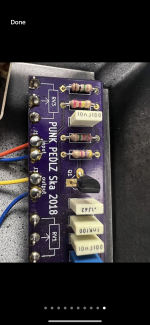
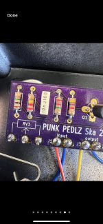
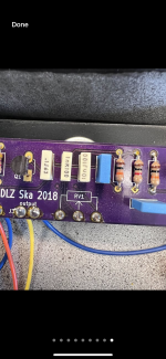
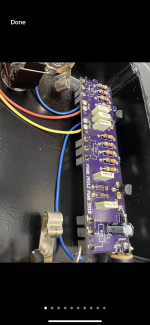
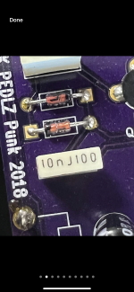
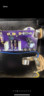
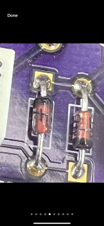
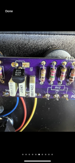
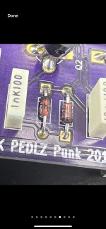
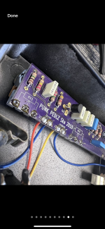
On reverb there were two pedals that were for sale by a music shop. The pedals were originally sold by one of my favorite bands and they only made a 100 of each and they are very expensive if they come up for sale… so I emailed the seller of these pedals and asked him if he could take pictures of both sides of the circuit board and give me the values or numbers of the components. So that I could possibly build one of theses pedals…. Well at first he sent me like 19 photos and when I told him I need to see the other side of the board and need to see the values of the pots… he said he would get back to me and never did until I asked for them again a week later… and he didn’t want to unsolder the 9v input plug. And the guy told me before I payed him that he builds and repairs pedals and amps…. Well here’s the question I was wondering if anyone recognizes what circuit these pedals are based off of. And or I doubt this would it be possible for anyone to figure out the schematics and recreate the pedals from these pictures and do maybe a point to point build or even better a pcb… if someone could sketch up a diagram of the two pedals if possible it would be awesome  thanks
thanksAttachments
-
 IMG_8129.png3.1 MB · Views: 122
 -
 IMG_8119.png3.5 MB · Views: 119
 -
 IMG_8120.png3.4 MB · Views: 110
 -
 IMG_8121.png2.9 MB · Views: 107
 -
 IMG_8122.png2.9 MB · Views: 104
 -
 IMG_8123.png3 MB · Views: 92
 -
 IMG_8125.png3.2 MB · Views: 98
 -
 IMG_8126.png3.1 MB · Views: 88
 -
 IMG_8127.png3.1 MB · Views: 90
 -
 IMG_8128.png3.4 MB · Views: 116


 I find that highly interesting, that a couple of BJTs can accomplish an op-amp sound!