You are using an out of date browser. It may not display this or other websites correctly.
You should upgrade or use an alternative browser.
You should upgrade or use an alternative browser.
Two LED’s in One Question…
- Thread starter Coda
- Start date
Bricksnbeatles
Member known well
I’ve tested it before. Better results from red/blue LEDs than red/green LEDs
You can also get an RGB led and just clip away the leg for whichever color you choose not to use. Or you could tie together two legs.
Gotta think of additive color theory. If you have Red as your status indicator and Green as your rate indicator, when you’re engaged, you’ll have red alternating with yellow.
If you do green as your status indicator, and then tie red and blue together for your rare indicator, then in bypass you’ll have flashing magenta as your rate indication, and engaged you’ll have alternating green and white.
You can also vary the CLR of different values to mix your own colors.

Coda
Well-known member
When I've used bi-color LEDs, I switched between them.
I'm not sure how they will behave if both anodes are connected at the same time.
For this build I was thinking that the cathodes would be shared. Thing is, the bypass LED goes to ground, the rate LED doesn’t.
Edit: saying that out loud, I realize I’m a dummy. Both LED’s go to ground (obviously). I was thinking of it in terms of the rate LED shutting off when the pedal is bypassed. Which is no big deal. I’m gonna try the common cathode…
Not sure why you're saying that the rate led doesn't go to ground... according to schematic, it does:For this build I was thinking that the cathodes would be shared. Thing is, the bypass LED goes to ground, the rate LED doesn’t.
Edit: saying that out loud, I realize I’m a dummy. Both LED’s go to ground (obviously). I was thinking of it in terms of the rate LED shutting off when the pedal is bypassed. Which is no big deal. I’m gonna try the common cathode…

Coda
Well-known member
Not sure why you're saying that the rate led doesn't go to ground... according to schematic, it does:
View attachment 50869
I meant the same ground. The bypass LED goes to ground through the switch. I was thinking that because the rate LeD would go out when the pedal was bypassed, it wouldn’t. But it would. It’ll just go off when the pedal does. That’s fine for me…
Oh... yes... Switch off, both color off... switch on, solid color and blinking "mixed" color for rate... that's what I understand.I meant the same ground. The bypass LED goes to ground through the switch. I was thinking that because the rate LeD would go out when the pedal was bypassed, it wouldn’t. But it would. It’ll just go off when the pedal does. That’s fine for me…
Feral Feline
Well-known member
When I built my Cowgirl (Madbean Wigl), I used the rate LED as my bypass LED, wiring the rate-LED's ground to the 3PDT's ground.
When the pedal is bypassed, the rate LED is bypassed, when pedal is engaged the rate-LED gets connected to GND. Simple.
Oh, and it's just a single-colour red LED (12mm) that I used for the dual-duty Rate/Bypass.
When the pedal is bypassed, the rate LED is bypassed, when pedal is engaged the rate-LED gets connected to GND. Simple.
Oh, and it's just a single-colour red LED (12mm) that I used for the dual-duty Rate/Bypass.
benny_profane
Well-known member
Feral Feline
Well-known member
Cool!
Feral Feline
Well-known member
No. I cannot think of any way you could convert common-cathode to common-anode — if you were to physically try that you'd break the LED's casing and destroy the LED. Not worth the time and effort to even try that, I'd just get the LED needed.Is it possible to make a common cathode LED a common anode LED, or are they stuck just the way they are?
It's not like twisting legs around on a transistor to adapt a different pinout.
This 4-pin RGB diagram might help in understanding how common cathode vs anode work:
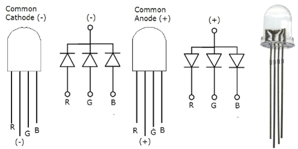
diagram from here:

Using Common Cathode and Common Anode RGB LED with Arduino
Common Cathode and Common Anode RGB LEDs are two different kinds of RGB LEDs whose function is same but working is different. By Techmirtz.
www.hackster.io
LED pinouts - 2, 3, 4-pin and more | LEDnique
Multi-colour devices use a variety of LED pintouts for 2-pin, 3-pin, 4-pin and 6-pin discreate packages.Lead length is used to guide assembly.
Hmmm... nonetheless, I found this RGB info:
Further info can be extrapolated here, maybe:

LED matrix : common anode vs common cathode is there a difference?
I was about to order some MAX7219 that are to be used with common-cathode led displays and I suspect the led matrix I have is common-anode (I have to find it and check). So that got me worried, but then I thought what if I interchange the rows and columns pins? will it not be the same? If the...
 forum.arduino.cc

Common Cathode VS Common Anode LED Displays
Common Cathode VS Common Anode LED, common anode means individual LEDs are connected via their positive ends and driven by negative ends.

Re-design for common anode instead of common cathode
I have a very simple circuit, and I want to use a tri-color LED to indicate which 1 of 3 outputs is on. I currently have a design that works for a common cathode 4-pin LED. However, I have easier AND
 electronics.stackexchange.com
Very difficult to find anode vs cathode topics based on 3-pin bi-colour format.
DeadAirMD
Well-known member
I only have common cathode, and have a ton of them, and unfortunately some GuitarPCB builds I've done only use common anode. Had no idea these differences even existed until I did some research as to why my LEDs were not working in those builds. Btw, I really appreciate all of that info, some great reads/watches to check out this weekend.
Similar threads
- Replies
- 3
- Views
- 148
- Replies
- 13
- Views
- 653
- Replies
- 7
- Views
- 690
- Replies
- 3
- Views
- 268