Thank you! I know, but I’m on a snouse BB2 kick lately, and I feel inadequate with only 3 switches. There’s no way I can gig with it only having 3 and everyone else has 4!
It's just an input cap switch.


Thank you! I know, but I’m on a snouse BB2 kick lately, and I feel inadequate with only 3 switches. There’s no way I can gig with it only having 3 and everyone else has 4!
It's just an input cap switch.
That threw me off initially as well, but according to a couple other builders (Breakfast Audio, Niche Devices), TL072 (dual op amp) runs on +17V/-17V, meaning ground, or better stated, “0V,” is half the op amp supply. If you think about the power supply as potential and absolute numbers, it makes sense.I tried it on the emulator software and that doesn't work. Maybe there's still something wrong in your schematic.
I advice to open a new thread about it. Maybe somebody can see what's this mistake, if it is there.
EDIT: I guess there's something about the bias of the op-amp. Check R1 and R5.
I understand what they are saying but the TL072IP datasheet says max 36V.That threw me off initially as well, but according to a couple other builders (Breakfast Audio, Niche Devices), TL072 (dual op amp) runs on +17V/-17V, meaning ground, or better stated, “0V,” is half the op amp supply. If you think about the power supply as potential and absolute numbers, it makes sense.
R5 is biasing the op amp. I’ve seen synths and studio equipment schematics that employ the same stuff as well. I also suspect R7 plays some sort of role as well but I am not sure and basing this purely on the Eunuch where R7 is connected to the bias voltage.
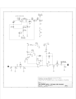
Furthermore, if you look at the Eunuch Buffer (https://www.pedalpcb.com/product/pcb581/), which is the Skeptical Buffer minus the elaborate bipolar voltage supply and runs on 9V/0V, R100 and R101 forms a voltage divider, equaling half the op amp power supply or 4.5V. (Eunuch can run at higher voltages, but 9V is the ‘starting’ voltage.)
I postulate that if you want the Eunuch to match the headroom of the Skeptical Buffer, you may need to run the Eunuch at 35V.
EDIT:
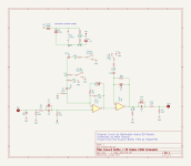
I have also attached a picture for what I believe is the Eunuch Buffer schematic so that you may try that in LTSpice or any other simulator. I pieced it together based purely on speculation and looking at the picture of the PCB on the product page.
Note:
- Pin 8 and 4 of IC1 are now attached to +V and ground (or 9V and 0V, respectively)
- The addition of the voltage divider network (R100, R101) and C11. The part values are numbers I pulled out of thin air, but as long as R100 and R101 are equal, the circuit should theoretically work.
- R5 and R7 are now attached to Vref (VEE, 4.5v).
I understand what they are saying but the TL072IP datasheet says max 36V.
Also if you run the Eunuch Buffer at 35V and the TL072 can only handle 17V wouldn't it fry the chip?
Vsupply is the max operating potential.understand what they are saying but the TL072IP datasheet says max 36V.
Also if you run the Eunuch Buffer at 35V and the TL072 can only handle 17V wouldn't it fry the chip?
Thanks for the updated schematic Robert!!
It's just an input cap switch.
I think I understand now. If pin 4 Vcc neg is connected to ground in the circuit, the input pins can handle the 36V.Vsupply is the max operating potential.
Vs=(V+)-(V-)
TL07X devices have a Vs_max of 42V. The 36V spec refers to the max on the input pins (i.e., common mode voltage and voltage differential), not the supply absolute.
So the extra input cap switch is part of the boost circuit only???
Man the normal Pot and Kettle is so easy to understand - boost, clip, smooth. The tight switch is not bad either, as long as you know it only works with boost enabled.
No but it certainly LOOKS incorrect I'm afraid. What sort of frequency response are you getting from the simulations?Can anyone verify the Euna schematic as correct?
Can anyone verify the Euna schematic as correct?
No but it certainly LOOKS incorrect I'm afraid. What sort of frequency response are you getting from the simulations?


Ask for help in the troubleshooting forum. Are you having trouble with your builds?Buy a PCB without a schematic? What should I do if I made a mistake or something is wrong?