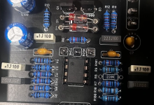
PPCB ADHD 2.0 Germ

Locrian99

Well-known member
Build Rating
5.00 star(s)
It feels like it’s been awhile since I’ve built anything been meaning to put this together for awhile but have had a hard time finding a parts list I trusted. Got a hold of a copy of the old adhd 2.0 schematic and figured out what’s what.

In case anyone is looking for it this is for the 2.0 for the germanium just add the diodes.
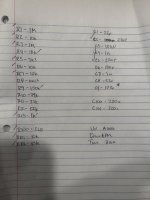
400EDC2D-6020-415E-90DD-B39834CBD30D.jpeg

C9 is not in the old 2.0 schematic but it’s in the power section right before the op amp so I left it in.


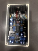
Build was pretty simple. I went ahead and used the buffer bypass board. Not sure why I used some of my few thru hole 5457 for a buffer instead of smd. Laziness I suppose :). I socketed the diodes which I typically don’t do but with this build I thought it made sense since they can be removed for a different version.

Buffer board worked awesome with some headers made for a very clean look.

This was my first build using my newly acquired rocket sockets. Highly recommend them. Also first time using this domed led bezel from tayda love the look. Though I wish I would’ve used a slightly larger clr 8.2k still isn’t big enough for the blue.

Sound wise… it sounds like an ocd to me. First time playing a 2.0 or germ variety but it’s been awhile since I’ve had an ocd around (gave last one
to a friend). From my memory this sounded fuller to me than the 1.4 did. Maybe a more bass and obviously with the germs a bit more compressed. I tried some 34a’s I had from SBP and some of the red band itt from small bear. I ended up with the red bands. They were a bit lower vf (.27) and I preferred that.

Enclosure is a cream powder coat from tayda.
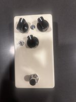
E91879A1-F0AB-48C0-9FF1-70357A975972.jpeg

CFDDC7F2-BE2D-4611-BD07-A2DD3A1662B5.jpeg
 
I was thinking of adding a charge pump board originally for 18v without having to use an 18v supply but much tighter in there than I realized. I still may try to do it at some point.
 
It feels like it’s been awhile since I’ve built anything been meaning to put this together for awhile but have had a hard time finding a parts list I trusted. Got a hold of a copy of the old adhd 2.0 schematic and figured out what’s what.

In case anyone is looking for it this is for the 2.0 for the germanium just add the diodes.
View attachment 65373

C9 is not in the old 2.0 schematic but it’s in the power section right before the op amp so I left it in.


Build was pretty simple. I went ahead and used the buffer bypass board. Not sure why I used some of my few thru hole 5457 for a buffer instead of smd. Laziness I suppose :). I socketed the diodes which I typically don’t do but with this build I thought it made sense since they can be removed for a different version.

Buffer board worked awesome with some headers made for a very clean look.

This was my first build using my newly acquired rocket sockets. Highly recommend them. Also first time using this domed led bezel from tayda love the look. Though I wish I would’ve used a slightly larger clr 8.2k still isn’t big enough for the blue.

Sound wise… it sounds like an ocd to me. First time playing a 2.0 or germ variety but it’s been awhile since I’ve had an ocd around (gave last one
to a friend). From my memory this sounded fuller to me than the 1.4 did. Maybe a more bass and obviously with the germs a bit more compressed. I tried some 34a’s I had from SBP and some of the red band itt from small bear. I ended up with the red bands. They were a bit lower vf (.27) and I preferred that.

Enclosure is a cream powder coat from tayda.
View attachment 65374

View attachment 65375
I noticed you used different pot values than what what the PCB calls for. Did you make these changes based on the schematic? Just curious
 
Yes the changes were made off the 2.0 schematic. The ppcb build docs specifically
The part numbers changed etc so I basically traced the board out to figure out which part number was which from the adhd 2.0 build docs before the new revision. It’s spot on and sounds perfect using those values. If you use the bypass board you can make an exact clone of the 2.0 using those values written on the paper above.
 
The part numbers changed etc so I basically traced the board out to figure out which part number was which from the adhd 2.0 build docs before the new revision. It’s spot on and sounds perfect using those values. If you use the bypass board you can make an exact clone of the 2.0 using those values written on the paper above.
Awesome! Thanks for putting in the work on this!
 
There's a mini-slide switch on the ADHD page, like it might be an option, but I don't see a spot for it on the circuit board?
 
There's a mini-slide switch on the ADHD page, like it might be an option, but I don't see a spot for it on the circuit board?
yes it is for if you use the bypass board. OCD 2.0 had the option of true or buffered bypass. There is an optional board (5$ if I remember right) to set this up. The switch is used to switch which bypass option. I used the bypass board in the pictures above.
 
I've built this pedal, and it is awesome. Way better than the OCD in my opinion. The buffered bypass option makes this pedal way more versatile than the OCD, depending on where you want to place it in your signal chain. I did swap out the drive pot for an A1M to make it respond more like the OCD V1.7, but @Robert really nailed this one.
 
yes it is for if you use the bypass board. OCD 2.0 had the option of true or buffered bypass. There is an optional board (5$ if I remember right) to set this up. The switch is used to switch which bypass option. I used the bypass board in the pictures above.
Thank you!
 
It feels like it’s been awhile since I’ve built anything been meaning to put this together for awhile but have had a hard time finding a parts list I trusted. Got a hold of a copy of the old adhd 2.0 schematic and figured out what’s what.

In case anyone is looking for it this is for the 2.0 for the germanium just add the diodes.
View attachment 65373

C9 is not in the old 2.0 schematic but it’s in the power section right before the op amp so I left it in.


Build was pretty simple. I went ahead and used the buffer bypass board. Not sure why I used some of my few thru hole 5457 for a buffer instead of smd. Laziness I suppose :). I socketed the diodes which I typically don’t do but with this build I thought it made sense since they can be removed for a different version.

Buffer board worked awesome with some headers made for a very clean look.

This was my first build using my newly acquired rocket sockets. Highly recommend them. Also first time using this domed led bezel from tayda love the look. Though I wish I would’ve used a slightly larger clr 8.2k still isn’t big enough for the blue.

Sound wise… it sounds like an ocd to me. First time playing a 2.0 or germ variety but it’s been awhile since I’ve had an ocd around (gave last one
to a friend). From my memory this sounded fuller to me than the 1.4 did. Maybe a more bass and obviously with the germs a bit more compressed. I tried some 34a’s I had from SBP and some of the red band itt from small bear. I ended up with the red bands. They were a bit lower vf (.27) and I preferred that.

Enclosure is a cream powder coat from tayda.

View attachment 65374

View attachment 65375
I just finished building this 'new' version, and I need to pick your brain a little, if you don't mind. So, I used the component values on the picture of the circuit board, and 34a's for the diodes. It works, but it's a little on the 'trebley' side, with not a lot of bottom end. If I turn the tone CCW, it just loses the highs (as expected), and it sounds like crap. I have a real V1 OCD for reference, if that maters. Since there is not available schematic yet, I can't compare the old version values you have listed to the new version. Also, I did not do the buffer board. Not sure if that even matters. I tried this build on 2 different amps with the same result. That said, any input or suggestions you (or anyone else here) may have is appreciated. TIA.
 
I just finished building this 'new' version, and I need to pick your brain a little, if you don't mind. So, I used the component values on the picture of the circuit board, and 34a's for the diodes. It works, but it's a little on the 'trebley' side, with not a lot of bottom end. If I turn the tone CCW, it just loses the highs (as expected), and it sounds like crap. I have a real V1 OCD for reference, if that maters. Since there is not available schematic yet, I can't compare the old version values you have listed to the new version. Also, I did not do the buffer board. Not sure if that even matters. I tried this build on 2 different amps with the same result. That said, any input or suggestions you (or anyone else here) may have is appreciated. TIA.
The values listed on the board are specifically 1.1 (there were 7 versions, though as I recall 5-7 were very similar and). Which version of the 1 are you comparing it to? There’s some pretty drastic differences.

First big one that pops is your version doesn’t have any of those germanium diodes unless you have a 1.4 at which point it’ll only have one. You’ll notice a more compressed sound here.

you most likely have a 1.7 that is the most current and I believe most common version. Like the 1.1 the actual values printed on the board are from is pretty hard to come by. And the most different. After 1.4 the changes were all pretty slim as I recall.

You’d probably end up closer to the 1.7 following the 2.0 values I posted above than using the 1.1.

The pdf there has the 2.0 schematic I got my values from. It doesn’t however match the part numbers listed on the board so you’ve got kind of trace it out to match them (I did that work for you on that picture of the notebook paper. Find which version you have, find a schematic of it online there’s plenty out there and see what the difference are.

I’d imagine the tone pot, gain pot and a couple of the cap values are going to be the big difference makers.
 

Attachments

  • ADHD.v2.pdf
    296.7 KB · Views: 30
The values listed on the board are specifically 1.1 (there were 7 versions, though as I recall 5-7 were very similar and). Which version of the 1 are you comparing it to? There’s some pretty drastic differences.

First big one that pops is your version doesn’t have any of those germanium diodes unless you have a 1.4 at which point it’ll only have one. You’ll notice a more compressed sound here.

you most likely have a 1.7 that is the most current and I believe most common version. Like the 1.1 the actual values printed on the board are from is pretty hard to come by. And the most different. After 1.4 the changes were all pretty slim as I recall.

You’d probably end up closer to the 1.7 following the 2.0 values I posted above than using the 1.1.

The pdf there has the 2.0 schematic I got my values from. It doesn’t however match the part numbers listed on the board so you’ve got kind of trace it out to match them (I did that work for you on that picture of the notebook paper. Find which version you have, find a schematic of it online there’s plenty out there and see what the difference are.

I’d imagine the tone pot, gain pot and a couple of the cap values are going to be the big difference makers.
To clarify, I just built the 'new' Pedalpcb ADHD version (https://www.pedalpcb.com/product/pcb542/), using the component values shown on the pedalpcb circuit board, since there are no build documents listed yet, and no schematic. MY Fulltone OCD is a Version 1.1, the first one they made. current pedalpcb ADHD shows germanium diodes. My original Fulltone V1.1 does not.
 
To clarify, I just built the 'new' Pedalpcb ADHD version (https://www.pedalpcb.com/product/pcb542/), using the component values shown on the pedalpcb circuit board, since there are no build documents listed yet, and no schematic. MY Fulltone OCD is a Version 1.1, the first one they made. current pedalpcb ADHD shows germanium diodes. My original Fulltone V1.1 does not.
The germanium diodes are there if you want to put them in. They should not be there if you are trying to recreate the 1.1.
 
The germanium diodes are there if you want to put them in. They should not be there if you are trying to recreate the 1.1.
There are two germanium diodes in the 2.0 ge version and 1 in the 1.4. All other versions do not have them. If you are trying to recreate the 1.1 I believe the parts listed minus the germs should get you there.
 
To clarify, I just built the 'new' Pedalpcb ADHD version (https://www.pedalpcb.com/product/pcb542/), using the component values shown on the pedalpcb circuit board, since there are no build documents listed yet, and no schematic. MY Fulltone OCD is a Version 1.1, the first one they made. current pedalpcb ADHD shows germanium diodes. My original Fulltone V1.1 does not.
This is the version I built too. When I built it I had an OCD Version 1.7 to compare it to. I followed the parts listed on the PCB with a couple of exceptions. Instead of the germaniums, I think I used shotkey diodes with a similar voltage drop. I also swapped out the drive pot for an A1M (if I recall correctly, the PPCB board called for a B500K). I used the A1M because that was what was on the OCD V1.7 that I had, and I liked the way the drive pot responded. I also experimented with a couple different Op Amps. I tried the 082, 072, and 071, but honestly I can't remember which one I ended up using, and I don't have the pedal anymore to check. I also see that you used a tantalum in C7 -- I think I used an electrolytic there, and I did not omit the 220K resistor in R8 -- not sure if either of those made a sonic difference, but I don't remember mine being trebley. I was pretty even across the spectrum.
 
There are two germanium diodes in the 2.0 ge version and 1 in the 1.4. All other versions do not have them. If you are trying to recreate the 1.1 I believe the parts listed minus the germs should get you there.
I wasn't really trying to recreate a specific version. It's just that my Fulltone V1.3 sounds better than the latest pedalpcb version to me. I'll try pulling the Germs. Thanks for the help/ Appreciate it.
 
Last edited:
This is the version I built too. When I built it I had an OCD Version 1.7 to compare it to. I followed the parts listed on the PCB with a couple of exceptions. Instead of the germaniums, I think I used shotkey diodes with a similar voltage drop. I also swapped out the drive pot for an A1M (if I recall correctly, the PPCB board called for a B500K). I used the A1M because that was what was on the OCD V1.7 that I had, and I liked the way the drive pot responded. I also experimented with a couple different Op Amps. I tried the 082, 072, and 071, but honestly I can't remember which one I ended up using, and I don't have the pedal anymore to check. I also see that you used a tantalum in C7 -- I think I used an electrolytic there, and I did not omit the 220K resistor in R8 -- not sure if either of those made a sonic difference, but I don't remember mine being trebley. I was pretty even across the spectrum.
Thanks. That's good info. I'll try a few of your suggested changes.
 
Back
Top