Intelligent Relay Bypass Module board updated (and other questions)

sIRwa2

New member
Hi, so TLDR, I bought the Intelligent Relay Bypass Module via musikding.de and it does not look like the version on the pedalpcb site.
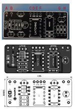
Intelligent RElay Bypass.jpg

the top PCB picture is the one that arrived... the bottom 2 are as currently on the website.

Now here's the thing, this is going to be my first build :S i thought, before starting something big, lets try a small, useful, and cheap utility kit.. Boy did i get a challenge :)

By all means, i enjoy this puzzle, but im afraid i need some help with this..

Question time:
1: Was there revision update on the pcb?
2: Can i have the bom list and schematic that matched this pictured pcb?
3: I noticed multiple ins and outs but i cant decode what is what. Please describe the ABCDEFGH for me. (im sorry for being blue)
4: Was the CTRL function removed? Was hoping to use that feature.

Thank you for your time..

O one more thing, whats the difference between the Basic Relay DPDT Switch (Latching) and the Intelligent DPDT Relay Module?
 
The board in picture 1 is the Basic Relay Bypass (Latching). Docs: Build Documentation

If you ordered the Intelligent Relay Bypass Module, you were sent the wrong board.

whats the difference between the Basic Relay DPDT Switch (Latching) and the Intelligent DPDT Relay Module?
The Basic DPDT isn't as smart. Really though, the full rundown is on the product page for the Intelligent DPDT. The difference with the intelligent version is that it add two additional momentary modes for three total modes [OFF-ON || ON-(OFF) || OFF-(ON)] where the basic version acts strictly like a DPDT switch [OFF-ON].
 
Sorry, I forgot about this...
Please describe the ABCDEFGH for me. (im sorry for being blue)

A. Connect to input jack tip
B. Connect to 9VDC supply
C. Connect to circuit board IN
D. Connect to circuit board -/GND
E. Connect to Cathode of LED or SW pad on PedalPCB board. Assumes LED Anode is connected to 9VDC through current limiting resistor (typically starts at 4.7KΩ).
F. Connect to circuit board OUT
G. Connect to primary ground supply
H. Connect to output jack tip
 
The board in picture 1 is the Basic Relay Bypass (Latching). Docs: Build Documentation

If you ordered the Intelligent Relay Bypass Module, you were sent the wrong board.


The Basic DPDT isn't as smart. Really though, the full rundown is on the product page for the Intelligent DPDT. The difference with the intelligent version is that it add two additional momentary modes for three total modes [OFF-ON || ON-(OFF) || OFF-(ON)] where the basic version acts strictly like a DPDT switch [OFF-ON].
You are correct, I guess the story would be the same here (Intelligent Relay Bypass Module vs Basic Relay Bypass Module) Too bad its not printed on the pcb
 
Sorry, I forgot about this...


A. Connect to input jack tip
B. Connect to 9VDC supply
C. Connect to circuit board IN
D. Connect to circuit board -/GND
E. Connect to Cathode of LED or SW pad on PedalPCB board. Assumes LED Anode is connected to 9VDC through current limiting resistor (typically starts at 4.7KΩ).
F. Connect to circuit board OUT
G. Connect to primary ground supply
H. Connect to output jack tip
Thank you for you quick and thorough reply. (My assumptions where right, but it' s really nice to have confirmation especially on a first build)

btw, is there an eta on the Intelligent DPDT Relay Module ?
 
The momentary function on the Intelligent relay is great for effects you just want to use for a few passages. I have it on my flange and vibrato pedals. The other soft touches are better for things you are going to leave on.
 
Back
Top