So...I've spent some time looking at this modification a bit further and I think I've answered one question but brought up another.
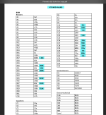
I used this site to calculate and verify the frequencies on the original (and bass version) Boss pedal, including the incorrectly labeled 6.4k value everyone seems to find. I also did some comparisons to the MXR pedal as well. This seems like the correct method and formula, so designing the circuit for the center of each adjusted frequency seems to work.
The next problem is determining the Q factor (aka quality or bandwidth). This is key in determining the width of frequencies affected. I went down a major rabbit hole, including: calculating Q for Boss & MXR pedals, calculating Q for rack mount 15 & 30 band equalizer schematics I could find, reading thesis papers, reading patents, etc!
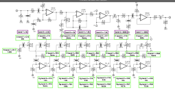
Why does this matter? When changing the gaps between frequencies, keeping the Boss Q values while changing to different gaps between frequencies may not create a desired outcome. Below shows the difference between a wide width (low Q) and therefore large overlap with bands and small width (high Q) and therefore small overlap with bands.


"Opting for a high Q will preclude control over the larger frequency gap, while opting for a low Q may result in large internal gains for the closely spaced bands"
What I found in my journey was a large variation in Q for octave-based graphic EQ design. I assume this is due to the designer making offsetting choices when determining their design. For the Boss pedals, Q typically ranged between 3 and 4. MXR between 2 and 3. I saw some rack mount EQs in the 5's. And these are all for octave EQs with the same frequency spacing! Now change it to randomly spaced frequencies selected by a Nashville session guitarist - who knows how they selected their Q values!
What surprised me was the lack of information online on circuit design strategy and the factors that should go into choosing a Q for a given frequency range. I found the straight conversion formula / table and one could theoretically convert the distance in frequency to the Q factor but the 5 circuits I analyzed were always larger than these conversions, meaning they look like the 2nd picture above and will have gaps in adjustment between frequencies.


I think options here are:
1. Someone who has purchased an XTS modded GE-7 provides the component values online (hoping, but hasn't happened and pedal out for years)
2. Someone provides references or guidance on how to chose a Q value when given a frequency range, whether straight conversion or other, and this guidance is followed to provide an optimum overlap with the XTS frequencies. I spent several hours searching and couldn't find anything. I'm sure this answer is lying in many out of print textbooks, somewhere.
3. I'm going to continue to hunt down 2/3 octave (in rack-world 15-band) graphic equalizer schematics and see if there's consistent approach and post a design here. If anyone else has a schematic on hand, I'd love to see a reply. This would not be an exact XTS replica, but instead would follow what I've found to be a standard frequency range of 400Hz, 630, 1k, 1.6k, 2.5k, 4k, with the option of having 250 on the bottom or 6.3k on the top for the 7th frequency. I'd probably opt for 250 on bottom. This may be the route I take anyways, since this feels like a nice halfway point between the XTS and Boss version.
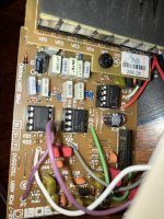
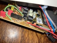
I just purchased a CE-2B / GEB-7 combo on eBay for a steal and the GEB-7 will make a perfect donor pedal for the conversion, so looking forward to working this project!
I used this site to calculate and verify the frequencies on the original (and bass version) Boss pedal, including the incorrectly labeled 6.4k value everyone seems to find. I also did some comparisons to the MXR pedal as well. This seems like the correct method and formula, so designing the circuit for the center of each adjusted frequency seems to work.
The next problem is determining the Q factor (aka quality or bandwidth). This is key in determining the width of frequencies affected. I went down a major rabbit hole, including: calculating Q for Boss & MXR pedals, calculating Q for rack mount 15 & 30 band equalizer schematics I could find, reading thesis papers, reading patents, etc!
Why does this matter? When changing the gaps between frequencies, keeping the Boss Q values while changing to different gaps between frequencies may not create a desired outcome. Below shows the difference between a wide width (low Q) and therefore large overlap with bands and small width (high Q) and therefore small overlap with bands.
"Opting for a high Q will preclude control over the larger frequency gap, while opting for a low Q may result in large internal gains for the closely spaced bands"
What I found in my journey was a large variation in Q for octave-based graphic EQ design. I assume this is due to the designer making offsetting choices when determining their design. For the Boss pedals, Q typically ranged between 3 and 4. MXR between 2 and 3. I saw some rack mount EQs in the 5's. And these are all for octave EQs with the same frequency spacing! Now change it to randomly spaced frequencies selected by a Nashville session guitarist - who knows how they selected their Q values!
What surprised me was the lack of information online on circuit design strategy and the factors that should go into choosing a Q for a given frequency range. I found the straight conversion formula / table and one could theoretically convert the distance in frequency to the Q factor but the 5 circuits I analyzed were always larger than these conversions, meaning they look like the 2nd picture above and will have gaps in adjustment between frequencies.
I think options here are:
1. Someone who has purchased an XTS modded GE-7 provides the component values online (hoping, but hasn't happened and pedal out for years)
2. Someone provides references or guidance on how to chose a Q value when given a frequency range, whether straight conversion or other, and this guidance is followed to provide an optimum overlap with the XTS frequencies. I spent several hours searching and couldn't find anything. I'm sure this answer is lying in many out of print textbooks, somewhere.
3. I'm going to continue to hunt down 2/3 octave (in rack-world 15-band) graphic equalizer schematics and see if there's consistent approach and post a design here. If anyone else has a schematic on hand, I'd love to see a reply. This would not be an exact XTS replica, but instead would follow what I've found to be a standard frequency range of 400Hz, 630, 1k, 1.6k, 2.5k, 4k, with the option of having 250 on the bottom or 6.3k on the top for the 7th frequency. I'd probably opt for 250 on bottom. This may be the route I take anyways, since this feels like a nice halfway point between the XTS and Boss version.
I just purchased a CE-2B / GEB-7 combo on eBay for a steal and the GEB-7 will make a perfect donor pedal for the conversion, so looking forward to working this project!
")