5F6/JTM45

Mike McLane

Active member
OK, I can't help myself. I had a Traynor Bassmaster (YBA-1) which is a clone of the '59 Bassman/JTM 45 and it was a glorious (but HEAVY) amp. So I've decided to sketch out a preliminary layout for a pedal version. I reviewed the original schematic, but also found this paired down layout from the Robrobinette site which appears to really fit the bill. Some values vary depending on whether you're looking at the original Fender schematic (the one I found on-line varied slightly from the one found on Robinette's site) or the one shown below which appears to have a "blackface" leaning to the tone stack. Still, some other component values will be required to result in a JTM45 (Robinette outlines those). I plan the unused A side of V1 for a front end single stage Boost. I would appreciate ANY comments or corrections. . . .
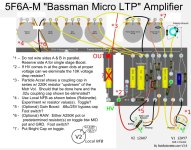
Micro 5F6 (annotaed).jpg
 
More power to you my dude. I've sworn off turret/eyelet board builds because I don't have the patience to do it carefully and I don't trust myself to do it right. I did turrets mounted on a PCB once so all the routing was taken care of, but it was a lot of extra steps for what was still just a PCB build.
 
In response to your questions:
  1. That's a personal choice. Personally I like the tone achieved by running tube stages in parallel, but I obviously understand the desire to have a boost available.
  2. It's certainly safe to do so, I typically remove all dropping resistors in preamp designs where I'm using an SMPS.
  3. That ones also a personal choice. If you want it to be CRAZY loud you can leave out the 220k resistor, but if you're planning to use this as a pedal feeding the front end of an amp rather than feeding a power amp, I would recommend having a resistor in there (potentially as high as 1M) to bring the output level down enough that you aren't blowing your eardrums out with the master volume at 9 o'clock.
  4. Personal choice, if that's something you want to try. Robinette's design has been done plenty, seems to work out for the people that have tried it.
  5. That would certainly be one way to achieve a boost. I would personally use a larger value cap, but 0.68uF is reasonable for a Marshall-esque value.
  6. I know you like doing that, and obviously I don't see a problem with it.
  7. I support this one. Marshall preamps tend to be a little too bright for my taste, and that's one of the things I do. My JCM preamp has the bright cab on one toggle and a second toggle to switch extra capacitors into the cathode bypass to open up the low end, so between the two switches I can get stock Marshall, slightly darker Marshall, and Lemmy-esque bass JCM tone.
 
Re 1: How does the parallel wiring differ from "normal" in tone terms?
Re 3: Do I also want the .022u coupling cap upstream of the 220K? Re: stouter resistor, I would want it to mirror the output characteristics of the Particle Accelerator. Does the cathode follower add any voltage that would necessitate the larger value? Does raise a related point. . . how to test the voltage output of a preamp.
Re 4: Are you aware of any source for a 16mm 50M pot? Its gonna see high voltage. Probably have to find one that doesn't physically fit and outboard wire it to test for 2 or 3 desirable values then use fixed resistors on a toggle. Will they have to be bigger than 1/4W? I bet so.
Re 5 & 7: Hmm. . . . with implementing cathode BP in both #5 & #7 you can go either Fender or Marshall. That is probably trying to serve too many masters for my first shot out of the gate. Probably stick with straight 5F6A (w/ RAW) for now. Gotta crawl before you can walk (don't even bring up chewing gum at the same time).

Thx for your input!! Got the DXF file!!
 
Last edited:
Re 1: How does the parallel wiring differ from "normal" in tone terms?
Re 3: Do I also want the .022u coupling cap upstream of the 220K? Re: stouter resistor, I would want it to mirror the output characteristics of the Particle Accelerator. Does the cathode follower add any voltage that would necessitate the larger value? Does raise a related point. . . how to test the voltage output of a preamp.
Re 4: Are you aware of any source for a 16mm 50M pot? Its gonna see high voltage. Probably have to find one that doesn't physically fit and outboard wire it to test for 2 or 3 desirable values then use fixed resistors on a toggle. Will they have to be bigger than 1/4W? I bet so.
Re 5 & 7: Hmm. . . . with implementing cathode BP in both #5 & #7 you can go either Fender or Marshall. That is probably trying to serve too many masters for my first shot out of the gate. Probably stick with straight 5F6A (w/ RAW) for now. Gotta crawl before you can walk (don't even bring up chewing gum at the same time).

Thx for your input!! Got the DXF file!!
  1. "Parallel tube design reduces the noise floor to vanishing point. In practical terms this means best possible signal to noise ratio for your guitar. It’s an expensive way of doing things, but it does yield stellar sound quality, without the compromise of noise gates or ‘cutting’ certain frequencies using equalisation." (source: Effectrode; they use parallel stages in a lot of their designs)
  2. Cathode followers are lower voltage but need a larger capacitor. I typically use 0.22uF (220nF) on cathode followers, but some people go as large as 220uF for hi-fi applications. For guitar a value of 220-680nF should be fine, and you can use a 50V cap without problem.
  3. 50M? Like 50MΩ? Like 50,000kΩ? I have never seen a pot that large in my life. What are you planning to do with a 50M pot?
 
What would I do with a 50M pot? If its as rare (i.e. non existent) as you say and I can find one I'll sell it at Southeby's for big $!! Seriously, if you'll look at the Robinette excerpt below you'll find he's spec'ing a resistor in the range of 22M-44M to go in series with a .047u cap. Something sound goofy about that? Maybe a misprint? But if its correct surely a 1/4W resistor is too punky. What should it be?

Local NFB how-to.jpg
 
What would I do with a 50M pot? If its as rare (i.e. non existent) as you say and I can find one I'll sell it at Southeby's for big $!! Seriously, if you'll look at the Robinette excerpt below you'll find he's spec'ing a resistor in the range of 22M-44M to go in series with a .047u cap. Something sound goofy about that? Maybe a misprint? But if its correct surely a 1/4W resistor is too punky. What should it be?
That value is fine as a resistor, but you're not going to find a pot that big, they just don't exist. If you want some variability you can do a 44M (if you can find a resistor that big) and throw another on a switch to parallel it to 22M. I haven't played with this myself, but it sounds like too low a value isn't going to be very useful, so you won't want to go down to zero, which means you may not find a pot there to be worth the trouble.

As for the resistor rating, this is where we dust off Ohm's law. If you're running 250V on your plates, then worst case scenario you're going to see 250V across that resistor. If your resistor is 44MΩ, then power dissipation across that resistor is going to be V²/R = 250²/44,000,000 = 0.00142W

You'll be fine with a 1/4W resistor there. BUT if you're running a pot, you're going to be in huge trouble because your minimum value is theoretically 0Ω, which means you will need a theoretically infinitely high rated potentiometer to handle it. So if you really want to use a potentiometer, put a 10M or so resistor in series with it so you have a minimum resistance and nothing will catch on fire.
 
From the discussion on cathode followers in the Particle Accelerator thread you indicated that the voltage coming out of the cathode follower is much lower than that coming off of the plate. If so what voltage cap would work in the tone stack. . . 25-50V as with "normal" cathode ground bypass caps? I note in photos that many of the builders are still using 630V caps.
 
From the discussion on cathode followers in the Particle Accelerator thread you indicated that the voltage coming out of the cathode follower is much lower than that coming off of the plate. If so what voltage cap would work in the tone stack. . . 25-50V as with "normal" cathode ground bypass caps? I note in photos that many of the builders are still using 630V caps.
Yup, 25-50V is perfectly fine. You will always find builders that use 630V caps throughout for the sake of consistency, but there are plenty of places in amplifiers that don't require it.
 
Now comes the Bright Switch conversation. . . do we really need one? There isn't one in the London Underground or Particle Accelerator. When the Volume knob is at 10 the bright cap has no effect. It's only when you turn down the volume the high end starts to go away. Since we're dealing with a PEDAL we can keep out Gain pot near 100% all the time unless you want squeaky clean at which point you turn down just enough to avoid clipping at full guitar signal? If we eliminate it would this just shove the "high end loss" issue down to the Volume pot?
 
Now comes the Bright Switch conversation. . . do we really need one? There isn't one in the London Underground or Particle Accelerator. When the Volume knob is at 10 the bright cap has no effect. It's only when you turn down the volume the high end starts to go away. Since we're dealing with a PEDAL we can keep out Gain pot near 100% all the time unless you want squeaky clean at which point you turn down just enough to avoid clipping at full guitar signal? If we eliminate it would this just shove the "high end loss" issue down to the Volume pot?
I never put bright switches in anything I build. I've never had the treble completely dimed and said to myself "you know what I want? even more brightness". I've always felt like a decent tonestack can get me all the brightness I will ever want.
 
Yeah, my wife wishes I had a decent tone stack (I guess you could take that a couple of ways)!?!? She accuses me of not being the brightest bulb in the box. Anyway, my next quandry. . . . I don't have any sense of how hot the signal is coming off of the tone stack in the 5F6A. The Particle Accelerator has the 220K "pad" preceding the Master Volume, but since we're coming off of a cathode follower do I eliminate it or sub a lower value? Is it just a matter of experimentation? While on the subject, I'm curious why Fender chose to put a simple in-line resistor as opposed to a voltage divider network. Do they both accomplish the same thing? I know the in-line would filter out highs to some extent (probably factored in when designing the circuit), but would the voltage divider do the same?
 
Question on 12AX7's. They're said to have a gain factor of 100. Is that "per side" or total of the output of both sides?
 
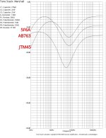
Just comparing tone stacks with the Duncan Tone Stack Calculator. . . '59 Bassman vs JTM45 vs Blackface AB763. I'm curious why the variance btw '59 & JTM45 as they have identical tone stack components. The '59 was "programmed" on the Fender tab and the JTM45 on the Marshall tab. Maybe there are some assumptions that are built into each tab that would render different outcomes. Any thoughts from anyone???

5F6A vs AB763 vs JTM45 tone stack comparison.jpg
 
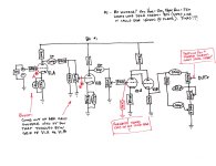
After wrestling with this and reviewing a number of schematics this is what I came up with this as a starting point. It's basically a Space Heater stuck on to the front end of a classic 5F6A schematic. I've decided to defer any issues regarding modifying the tone stack, etc. for now. My biggest concern is over proper "transitions". . . coupling caps, grid leak resistors, etc. . . btw the gain stages, tone stack & output jack. Looking for comments.
5F6A MJM schematic, Rev 0.jpg
 
After wrestling with this and reviewing a number of schematics this is what I came up with this as a starting point. It's basically a Space Heater stuck on to the front end of a classic 5F6A schematic. I've decided to defer any issues regarding modifying the tone stack, etc. for now. My biggest concern is over proper "transitions". . . coupling caps, grid leak resistors, etc. . . btw the gain stages, tone stack & output jack. Looking for comments.
View attachment 48630
  1. "boost" should be fine, but if you put point B before the gain pot you can have a variable level of boost.
  2. Adding the 330k isn't a bad idea, but not probably not crucial.
  3. My understanding is that 220k pots are more common in Europe, and 250k pots are more common in the states. This is why we use 250k.
  4. Space Heater and PA both use a B+ of about 240V, but my documentation is inconsistent on how I label it. The SMPS I use can easily go up to 325V, just make sure you use at least 400V rated filter cap.
 
Thx, Nathan! I'm confused about #1. . . I was thinking that with B where it is currently shown it would function as you indicate, but ONLY when the Boost circuit is activated. Otherwise the signal would completely bypass the Boost stage (including the A1M pot) and enter the V1.B grid directly from the 68K grid stopper. . . just like a conventional 5F6A schematic. What am I missing (besides a few brain cells)? As to #3. . . Where are you refering to 220K pots . . . immediately preceding the Master Vol? That should be a 220K resistor as in the Part Acc & AB763 schems. However, given that this is a GAIN->GAIN->TONE STACK configuration w/ cathode follower I don't know how the output level will vary from the G->TS->G configuration of the Part Acc/AB763. I would guess relatively similar, albeit a bit more "gainy". Also, I know the cath follower should lower the output impedance and if I read my "Robinette" correctly one purpose of the cath follower is to help preserve signal strength thru the TS. So I would guess that if anything the signal level is => the Part Acc so some resistor "pad" would be called for.
 
I misunderstood where you were talking about the 220k there, I thought you were referring to the value of the treble pot. An inline resistor at the end to drop the output level is really going to depend on your application. If you're planning on using this as a pedal running into the front of an amp, omitting the dropping resistor will give you an absurdly hot output, to the point where your volume pot will be useless anywhere above 9 o'clock and you won't have much usable sweep at all. If you're pushing a power amp, it's a pretty good idea to leave it out so you can get the most juice possible out of the preamp.
 
Back
Top