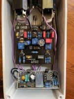
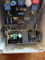
Trying to use a relay bypass for the first time in an Acrylic Overdrive (Wampler Plexi Drive) pedal I was putting together. The relay reliably turns on the effect but it has trouble turning it off/bypassing the effect. I'm trying to narrow down the issue before I just rip it out and just go with a standard 3PDT footswitch.
Here's what I'm seeing:
I did use a tantalum 1uf cap in place of the 1uf MLCC specified in the docs. Could that affect the behavior?
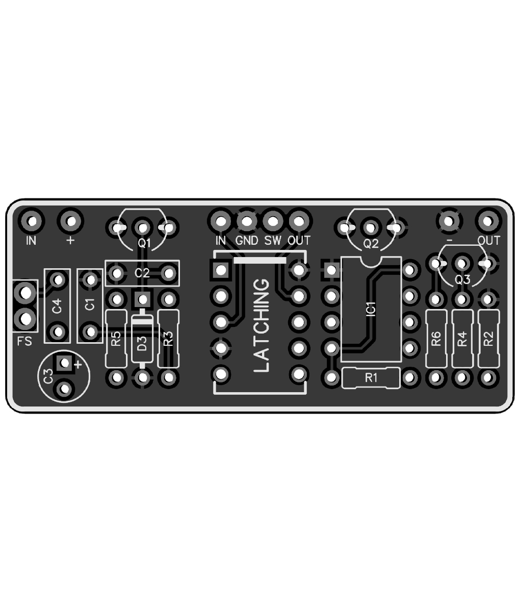
I tested the momentary footswitch with my DMM before I did anything else- I confirmed it's a normally off momentary switch by testing continuity. I had another NE555 IC on hand and tried that but same behavior. I'm using a TQ2-L-5V and I verified I'm using the right transistors, which I got from Mouser.
Anyone had similar issues, or have any suggestions?
Not the end of the world- I can just swap out for a standard footswitch if I can't figure it out, but just disappointed my first try at using relays isn't working.
Here's what I'm seeing:
- When first applying power, the LED is off and effect is bypassed
- Upon pressing footswitch, the LED turns on and the effect is active. This works 100% of the time
- Pressing footswitch again, nothing happens 95%+ of the time. The effect and LED remain on. Pressing the switch dozens of times, the relay eventually switches and bypasses the effect. I can't seem to find a pattern of when it actually works- just very intermittent.
- Once off, the switch reliably turns the effect back on 100% of the time.
I did use a tantalum 1uf cap in place of the 1uf MLCC specified in the docs. Could that affect the behavior?
I tested the momentary footswitch with my DMM before I did anything else- I confirmed it's a normally off momentary switch by testing continuity. I had another NE555 IC on hand and tried that but same behavior. I'm using a TQ2-L-5V and I verified I'm using the right transistors, which I got from Mouser.
Anyone had similar issues, or have any suggestions?
Not the end of the world- I can just swap out for a standard footswitch if I can't figure it out, but just disappointed my first try at using relays isn't working.