Bring out yer Diptrace

It's nice to see this thread still kicking at 10 pages. Obviously a lot of interest in taking DIY to the next step.

Here's what I've been working on:

Kaiju DIstortion.png
Kaiju in box.png
It's a modified Life/Parentheses. I've recently fallen in love with this circuit, after realising how nicely it can be used as a dirty octave boost into a cranked Rectifier for crushing, reptilian doom tones (hence the Kaiju name). I've switched in an op-amp boost and also modified both buffer stages. The Rat and Ringer portions of the circuit are pretty stock. Should be fun to build and I already have a mate asking for one when I've verified the circuit.

Edit: Only one major symmetry cheat this time. Robert has ruined me with this strategy of putting fake parts on the board to make the silkscreen symmetrical haha
 
It does. You need to "save as" not export.

Another dxf tip: in illustrator I use the “Add Points” function 5+ times before exporting as dxf. I’m not sure if it’s the dxf standard itself or diptrace’s handling of it but not doing this gives shitty results. Not sure what this function is called in other vector software but I gotta imagine it’s in the rest.
 
The Skewer fuzz: what you get when you combine a Meathead and a Doomstick II. (Meat + stick = skewer). I thought I would squeeze two one-knob fuzzes into a 125B and have them on a switch. I decided against 2 footswitches as I don't like 2 in this size enclosure. Using an on-on-on switch allows for a 3rd mode that combines the fuzzes. No symmetry cheats on this board for once.

Skewer Fuzz.png
 
I've been on a bit of a tear with PCB design lately. This one is a result of playing around with the El Sol/Acapulco schematic. I found something reasonably funny while looking through LM386 datasheets, namely that the Acapulco Gold - famed pedal "based on the sound of a cranked Sunn Model T" - is actually just two of the example circuits from the LM386 datasheet back-to-back with an RC filter between them and a voltage divider at the output. The marketing department's fun little story about an obscure tube amp that 99% of guitarists (including me) couldn't recognise in a blind sound test is a stroke of genius.

Kolossus Distortion.png

Anyway, I wanted to add a gain control to give texture options, so I put a pot in series with the 10UF cap in the first LM386's gain loop. This means I can move between a lower gain all the way up to the stock Acapulco gain of 200. I added bypass caps for the biasing section of each LM386 as this can help with power supply noise. I also added in a James tone stack and will fine-tune the values once I do a test build. Lastly I gave the second amplification stage a slightly higher output to offset the insertion loss from the tone stack and any less-than-full-bore gain settings from the first amplification stage. Should still be a loud, aggressive pedal, but one with more tonal options than the original.
 
Last edited:
I've been on a bit of a tear with PCB design lately. This one is a result of playing around with the El Sol/Acapulco schematic. I found something reasonably funny while looking through LM386 datasheets, namely that the Acapulco Gold - famed pedal "based on the sound of a cranked Sunn Model T" - is actually just two of the example circuits from the LM386 datasheet back-to-back with an RC filter between them and a voltage divider at the output. The marketing department's fun little story about an obscure tube amp that 99% of guitarists (including me) couldn't recognise in a blind sound test is a stroke of genius.

View attachment 49825

Anyway, I wanted to add a gain control to give texture options, so I put a pot in series with the 10UF cap in the first LM386's gain loop. This means I can move between a lower gain all the way up to the stock Acapulco gain of 200. I added bypass caps for the biasing section of each LM386 as this can help with power supply noise. I also added in a James tone stack and will fine-tune the values once I do a test build. Lastly I gave the second amplification stage a slightly higher output to offset the insertion loss from the tone stack and any less-than-full-bore gain settings from the first amplification stage. Should still be a loud, aggressive pedal, but one with more tonal options than the original.
There are so many reference architectures in pedals. Basically any pedal with a THAT chip is a good example.
 
I guess that’s what the data sheet is there for, to show a reference architecture for people to implement and sell.

It’s always nice to improve on something or add a bit more value to the user though.
It's not lost on me that some of my tweaks to the circuit came from the datasheet too. I wouldn't then claim that my variant of this circuit is designed to sound like an obscure and expensive amplifier. It's the exaggerated claims when all they've done is configure the part according to the manufacturer's suggestions that I find amazing.
 
Some more utility boards.

A splitter / blender. Jumper one side for a clean blend (no phase switch, let's see how this one works first).
1686052090517.png
A smart relay breakout board. Two relays and a single footswitch. Holding the footswitch turns on the (optional) second relay which you can use as a DPDT for whatever your heart desires.
1686052190065.png
 
Some more utility boards.

A splitter / blender. Jumper one side for a clean blend (no phase switch, let's see how this one works first).
View attachment 49976
A smart relay breakout board. Two relays and a single footswitch. Holding the footswitch turns on the (optional) second relay which you can use as a DPDT for whatever your heart desires.
View attachment 49977
Sweet! I'm just revisiting various utility boards I whipped up during The Plague, as I'm going to need some blender and splitter circuits for a few customer jobs right quick. This one has two inverting inputs and two non-inverting, for instance:

SM_3_3.PNG

SM_3_3_bare.PNG

I love doing little modules like this, time to start doing some pot mounted ones too though.
 
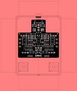
Runoff Groove's Splitter Blend. Not sure when/if I'll actually get it fabbed. Stealing @Grubb's way of screenshotting with pleasant backgrounds.
Even if you don't get it fabbed, it's good practice and fun to do. Your layout is really nice and clean. And symmetrical, which shouldn't really matter, but does to me.

In turn, I stole the background colour idea from some Pirate Midi product shots. Coral goes so nicely with black.
 
Even if you don't get it fabbed, it's good practice and fun to do. Your layout is really nice and clean. And symmetrical, which shouldn't really matter, but does to me.

In turn, I stole the background colour idea from some Pirate Midi product shots. Coral goes so nicely with black.

I'd say 1/3 of the time I'm at my computer at work I'm just dicking around laying out PCBs that I won't get made just for the fun of it lmao
 
Those TH/SMD transistor patterns look great. Tempting to migrate to something similar myself.

Damn all your symmetry on your designs!! I keep trying to convince myself that the Blohm & Voss BV 141 is a beautiful design..

The symmetry is a curse, I would have so many boards fabbed if I could handle how incongruently laid out they are. Also the smt hybrid jfet footprint is the move, definitely helps reduce any “is this build actually worth a jfet” I might get from a board of my own
 
The symmetry is a curse, I would have so many boards fabbed if I could handle how incongruently laid out they are. Also the smt hybrid jfet footprint is the move, definitely helps reduce any “is this build actually worth a jfet” I might get from a board of my own
Care to share that hybrid jfet footprint? It's on my to do list to create one and that would save me
 
Back
Top