You are using an out of date browser. It may not display this or other websites correctly.
You should upgrade or use an alternative browser.
You should upgrade or use an alternative browser.
Bring out yer Diptrace
- Thread starter Grubb
- Start date
Grubb
Well-known member
Help or not, if that's your first attempt, I have no doubt you're also going to be really good at this!Some of you guys are really good at this! Here's my first attempt, and I had a lot of help.
vigilante398
Authorized Vendor
I'm still thinking about my NAMM experience last week, and in my daydreaming I thought about what I want to do when I get a booth. Most pedal companies used headphone amplifiers so you can get a quieter listening experience, but it made me realize I hate the sound of most headphone amplifiers out there. So I designed an OTL (output transformerless) tube headphone amp. It should be good for headphones down to 30Ω, so I'm excited to try it out and see if it's going to work the way I want it to. It won't fit in a pedal enclosure, but it should fit in an 8"x4"x2" chassis.


Last edited:
iamjackslackof
Well-known member
As someone about to order the Bottlehead Crack OTL tube amp, I would totally buy and build this!So I designed an OTL (output transformerless) tube headphone amp
Mentaltossflycoon
Well-known member
Same, not the bottlehead, but same.As someone about to order the Bottlehead Crack OTL tube amp, I would totally buy and build this!
vigilante398
Authorized Vendor
As someone about to order the Bottlehead Crack OTL tube amp, I would totally buy and build this!
It's actually a fairly straightforward design, I was thinking about making it available as a project if I liked it. I'll let everyone know. You need a power transformer and a chassis, and the power tube is a 6AS7G which isn't a common one, but otherwise should be fairly easy to put together if you've ever built an amp (or even a reasonably complex pedal).Same, not the bottlehead, but same.
vigilante398
Authorized Vendor
My last PCB order hasn't even shown up yet (ETA is thursday) but I'm already ordering this and it's @Passinwind's fault. A tube mic preamp has been on my list for about two years now, and he finally convinced me to take a swing at it. It's a mixed design, all the power supply stuff is SMD and all the signal path stuff is through-hole. It's going to be expensive, so it better turn out cool or I'm going to be upset.


Harry Klippton
Not Interested
Is there a trick to bringing in artwork for the top silkscreen layer? It seems like diptrace wants to re-vector my vector artwork and screwing it up. I'm making my designs in inkscape, exporting to a PNG, then using "add picture" to the top silk layer, since I can't import an .svg to diptrace. Is there a better way to do this?
Smrtokvitek
Well-known member
Export as DXF from your vector drawing program and import it in Diptrace as a layer of your preference. It is a bit clumsy and you need to find the config that works. If I remember correctly everything needs to be in curves.
Harry Klippton
Not Interested
Edit: nope that wasn't it.
Last edited:
Harry Klippton
Not Interested
Looks like kicad supports.svg import 
vigilante398
Authorized Vendor
I thought I remembered diptrace taking jpeg and other image files directly and converting them on the backend, does it not do that?
Compared to diptrace, Altium's handling of graphics is actually a little clunky.
Compared to diptrace, Altium's handling of graphics is actually a little clunky.
Harry Klippton
Not Interested
It does, but diptrace does a really shitty job at it and makes it look all chunky
Smrtokvitek
Well-known member
have you tried the DXF method I have mentioned?It does, but diptrace does a really shitty job at it and makes it look all chunky
There is also this project but I haven't tried it yet. You could convert SVG to gerber and import it into your project.
GitHub - jaseg/gerbolyze: Directly render SVG overlays into Gerber and Excellon files
Directly render SVG overlays into Gerber and Excellon files - jaseg/gerbolyze
Harry Klippton
Not Interested
Inkscape doesn't export to DXF.have you tried the DXF method I have mentioned?
There is also this project but I haven't tried it yet. You could convert SVG to gerber and import it into your project.

GitHub - jaseg/gerbolyze: Directly render SVG overlays into Gerber and Excellon files
Directly render SVG overlays into Gerber and Excellon files - jaseg/gerbolyzegithub.com
I found this yesterday and I'm going to try it
Smrtokvitek
Well-known member
It does. You need to "save as" not export.
benny_profane
Well-known member
How did this board end up turning out for you? The layout looks very slick.I was looking at the Spaceman Gemini IV
flemming
Well-known member
I was breadboarding it from my schematic and realized I left out a couple components and I haven't gotten back to it yet. Squeezing a few more things in isn't such an easy task. No promises as to when I'll do that yet. It's on my list.How did this board end up turning out for you? The layout looks very slick.
szukalski
Well-known member
A couple of recent activities.
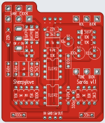
After many attempts, I finally got this Klon derivative in a place I am happy with. Dylan159 Centaur Clown with clipping options. The LED give a wicked edge and the BAT41s sound like the magic ones.

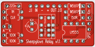
An improved basic relay layout. Takes both footprints of the relay I like, and you can lay the 47u flat to reduce the height.
You can also attach the SPST with solid core and the LED will align with Robert's enclosure standards, or you can attach the relay to the PCB with pin headers and wire with a LED bezel. I like the look of a naked LED poking it's butt through an enclosure, but the header approach is a lot easier.

After many attempts, I finally got this Klon derivative in a place I am happy with. Dylan159 Centaur Clown with clipping options. The LED give a wicked edge and the BAT41s sound like the magic ones.

An improved basic relay layout. Takes both footprints of the relay I like, and you can lay the 47u flat to reduce the height.
You can also attach the SPST with solid core and the LED will align with Robert's enclosure standards, or you can attach the relay to the PCB with pin headers and wire with a LED bezel. I like the look of a naked LED poking it's butt through an enclosure, but the header approach is a lot easier.


