
modularblur
New member
Hello!
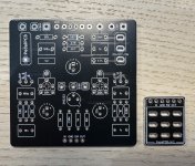
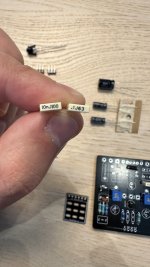
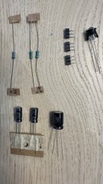
Just got a Chop Shop v2 and it will be my first pedal build. I was looking at some images around and I can't seem to find a circuit similar to my mine anywhere.
Can someone post me an actual finished job of this same exact circuit (image attached)? I don't want to mess up anywhere!
Thank you very much!
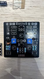
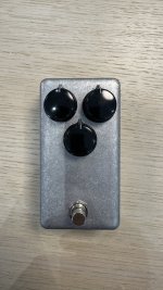

") Looks too good for the ordinary, cheap box.
Looks too good for the ordinary, cheap box.