

The Gator
Well-known member
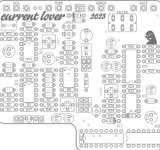
So an old friend of mine wanted a flanger different than his Boss flanger. So I decided to give a go at the current lover.
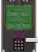
On my pedalpcb builds I like to reduce overall wiring by utilizing the daughter boards that Robert has to offer. The bypass switch boards and the I/O power boards. I noticed a lot of you do not use them. Not sure if it is a cost thing or what, but I recommend them if you want to reduce wiring in your pedals.
My question is, does anybody see a reason why I couldn't utilize the pedapcb boards in this current lover build?
Looks like the switch pinout on the board is the same.
Thanks
Gator
Attachments
Last edited:
