You are using an out of date browser. It may not display this or other websites correctly.
You should upgrade or use an alternative browser.
You should upgrade or use an alternative browser.
Deofol OD
- Thread starter HamishR
- Start date
Chuck D. Bones
Circuit Wizard
You do not need to match or select them. This circuit is very forgiving of JFET DC parameters. It will have a TON of gain. You might consider using a larger box and making some or all of the trimmers front panel pots.
I used to have an Okko Diavolo way back when, so I know what they sound like. I remember liking the pedal hence my wanting to build one. I have built some Menatone kinda pedals using J201s before and it was critical to bias them just right so I was hesitant about the Deofol. So thanks for quelling my fears! The board has been ordered...
Well that's a bit disappointing. Built my Deofol today, took extra care to get it right because it will be a bit of a PITA to take it out again if there is an issue. And it works but it really doesn't sound very good. The Presence trimmer does next to nothing but everything else does more or less what it should. The pedal just sounds a bit flat and I need treble up way high for it to sound at all balanced. I have the bass trimmer on zero but it still sounds a bit too bassy. Overall it sounds like badly biased Jfets. I'll put it to one side and have a look again when I can be bothered.
FWIW the space for the capacitors is a bit tight. I had to use cheaper grey 1µF caps because there was no way WIMAs were going to fit. And even with the grey box caps the caps barely fitted on the board.
FWIW the space for the capacitors is a bit tight. I had to use cheaper grey 1µF caps because there was no way WIMAs were going to fit. And even with the grey box caps the caps barely fitted on the board.
chongmagic
Well-known member
Well that's a bit disappointing. Built my Deofol today, took extra care to get it right because it will be a bit of a PITA to take it out again if there is an issue. And it works but it really doesn't sound very good. The Presence trimmer does next to nothing but everything else does more or less what it should. The pedal just sounds a bit flat and I need treble up way high for it to sound at all balanced. I have the bass trimmer on zero but it still sounds a bit too bassy. Overall it sounds like badly biased Jfets. I'll put it to one side and have a look again when I can be bothered.
FWIW the space for the capacitors is a bit tight. I had to use cheaper grey 1µF caps because there was no way WIMAs were going to fit. And even with the grey box caps the caps barely fitted on the board.
Did you socket the J201s or did you use SMD?
Hey, I am having a very similar issue. So I'm wondering if you figured what the issue was. If so, please let me know. Thank you!Well that's a bit disappointing. Built my Deofol today, took extra care to get it right because it will be a bit of a PITA to take it out again if there is an issue. And it works but it really doesn't sound very good. The Presence trimmer does next to nothing but everything else does more or less what it should. The pedal just sounds a bit flat and I need treble up way high for it to sound at all balanced. I have the bass trimmer on zero but it still sounds a bit too bassy. Overall it sounds like badly biased Jfets. I'll put it to one side and have a look again when I can be bothered.
FWIW the space for the capacitors is a bit tight. I had to use cheaper grey 1µF caps because there was no way WIMAs were going to fit. And even with the grey box caps the caps barely fitted on the board.
")
Chuck D. Bones
Circuit Wizard
Hey, Blivjc & Hamish, if you're still having trouble with this pedal, we can check the JFET biasing with a multimeter. First verify Vcc is around +17V and Vref is around +8.5V (switch in the 18V position). If those check out, measure each JFET Source (middle pin of the thru-hole device). Q1, Q5 & Q6 should be around +1V. Q2, Q4 & Q7 should be around +9.5V. Q3 should be pretty close to 0V. There's really nothing to adjust, we're doing this to verify that the JFETs and a few resistors are good. As for the lack of high-end, there aren't too many things that could kill the treble except the wrong value for C3.
Anotherpedalbuild
New member
This was a nightmare build. I bought two boards, and junked the first as it was a version 1 and the current build pdf is a version 2. I think that a couple of the diagrams on the pdf are V1.
I've got a genuine Diablo, and wanted to build a spare.
Here's my thoughts:
Matching the jfets didn't stop the screeching. I matched them, socketed them etc and used genuine units. The whistling and screeching was even present when the effect was bypassed.
The boost on the original Diablo only works when the fx is on. On the Deofol, the boost can be switched on independently. I rerouted the wiring to act like the Diablo.
There's way too much gain, far more than the Diablo.
The R23 & C19 whistling/screeching fix works, but the C19 (10nf) addition blunts the treble badly. The Diablo sounds nice and crisp, the 10nf won't allow this crispness.
I'm not claiming to be a guru, but I wanted to point out my fixes to save some other people from the frustration and lost parts which I had.
My fixes were:
Using a board mounted gain pot rather than the right angled pcb mounted type. I used wire for lugs 1 and 2. I used a 1meg resistor between the pcb and lug 3. This scrubs gain, and alleviates the whistling.
Use a 1n8 cap for C19. This was the lowest value to minimise the whistling.
I used a jump wire on R23.
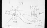
I wired the on/off foot switch as a master switch using the boost foot switch as a subsidiary loop of the master on/off foot switch.
To kill the ghost whistling audible when the fx was in bypass, I put a 470pf cap between the master foot switch 'fx in' tag and the ground tag of the switch.
This circuit design seems to be extremely unstable (the Okko design) and it was a nightmare build.
After two boards, I have a usable unit but the Okko is definitely better. For a cheap backup, the Deofol is great. I recommend using the Triangulum boost or Isosceles boost in front of it.
I've got a genuine Diablo, and wanted to build a spare.
Here's my thoughts:
Matching the jfets didn't stop the screeching. I matched them, socketed them etc and used genuine units. The whistling and screeching was even present when the effect was bypassed.
The boost on the original Diablo only works when the fx is on. On the Deofol, the boost can be switched on independently. I rerouted the wiring to act like the Diablo.
There's way too much gain, far more than the Diablo.
The R23 & C19 whistling/screeching fix works, but the C19 (10nf) addition blunts the treble badly. The Diablo sounds nice and crisp, the 10nf won't allow this crispness.
I'm not claiming to be a guru, but I wanted to point out my fixes to save some other people from the frustration and lost parts which I had.
My fixes were:
Using a board mounted gain pot rather than the right angled pcb mounted type. I used wire for lugs 1 and 2. I used a 1meg resistor between the pcb and lug 3. This scrubs gain, and alleviates the whistling.
Use a 1n8 cap for C19. This was the lowest value to minimise the whistling.
I used a jump wire on R23.
I wired the on/off foot switch as a master switch using the boost foot switch as a subsidiary loop of the master on/off foot switch.
To kill the ghost whistling audible when the fx was in bypass, I put a 470pf cap between the master foot switch 'fx in' tag and the ground tag of the switch.
This circuit design seems to be extremely unstable (the Okko design) and it was a nightmare build.
After two boards, I have a usable unit but the Okko is definitely better. For a cheap backup, the Deofol is great. I recommend using the Triangulum boost or Isosceles boost in front of it.
Anotherpedalbuild
New member
Hi, sorry to bump an old tread, but I have an issue with too little gain in my build. I have to bump FEED to max and BODY to min
to get any breakup. The boost part seems to work OK, though I haven't tested it much. I'm using MMBFJ201, soldered to the board (a major PITA!).
My measurements:
Vcc: 16.9 V
Vref: 8.45 V
Q1 source 1.33 V
Q2 source 7.42 V
Q3 source 0.14 V
Q4 source 7.92 V
Q5 source 3.78 V
Q6 source 0.38 V
Q7 source 9.49 V
Maybe someone could offer advice on what to check from the board? Is the biasing wrong?
Chuck D. Bones
Circuit Wizard
Hi, sorry to bump an old tread, but I have an issue with too little gain in my build. I have to bump FEED to max and BODY to min
to get any breakup. The boost part seems to work OK, though I haven't tested it much. I'm using MMBFJ201, soldered to the board (a major PITA!).
My measurements:
Vcc: 16.9 V
Vref: 8.45 V
Q1 source 1.33 V looks good
Q2 source 7.42 V too low, should be higher than Vref
Q3 source 0.14 V looks good
Q4 source 7.92 V too low, should be higher than Vref
Q5 source 3.78 V might be ok, where were BASS & TONE pots set when this measurement was taken?
Q6 source 0.38 V looks good
Q7 source 9.49 V looks good
Maybe someone could offer advice on what to check from the board? Is the biasing wrong?
According to your measurements, the gate voltage is higher than the source voltage on Q2 & Q4. For NJFETs, the gate voltage should never be higher than the source voltage.
Things that might be wrong on the board:
Q2 & Q4 drains not connected to Vcc.
Q2 & Q4 are damaged or fugazi.
R6 & R10 wrong value.
So, next day there was again very weak sound.
Probably a bad solder joint.
I bought more mmjf201s, soldered them on adapter boards,
measured with Run Off Groove's jfet tester 2.0, and messed with
my solder joints until I got a set of 7 jfets with similar, stable
Idss and Vp. BTW, it is better to use leftover leads from resistors
etc. instead of pin headers for the adapter boards because those
do not fit in the sockets of the jfet tester.
Now the pedal works very well, nice breakup and cleans up nicely with
guitar volume. For reference, the Idss range of my fets is .63 - .68 mA and
the Vp range is .82 - .86 V.
synchu
New member
Another bump of an old one, same problems though. This pedal drives me crazy - after fixing a bad trace between R6 and Q1 drain which took some hours. Don't know whether this is due to this specific board gone bad, but whatever.
I got the poor thing working and sounding just plain bad with no attack and mid-high, high frequencies at all. Did some head scratching exercise, and some googling 'till managed to find the issue, e.g. the supposed "fix" of 39k/10n that's setting what is rather extreme Low pass filter.
I took the effort to model the thing in Micro Cap and passed couple of analysis stepping the low pass cap value from 1pF to 10nF (through some common values - 220pf, 470pf, 1nf, etc.) and below are the results - green - captured at R12 and blue at the output). As one might see and definitely hear - there's quite a bit of difference - and it sounds nowhere near as good as when this 10nf cap is removed or at least decreased to a more sensible value.

Now, when it is removed the reason for it becomes obvious - the pedal sounds absolutely phenomenal, until you raise the gain/level - it oscillates like crazy - and after some time spent with matching all different varieties of J201 (SMDs and a bunch of NOS Fairchilds), changing few cheap ceramics that came with the kit purchased, I tend to think there's something with the PCB layout going on here.
I am not keen on purchasing a different kit with a different PCB (as at this point I well may have purchased a 2nd hand Diablo). I definitely can play with the biasing (and intend to do so - starting with Q3 source resistor), but this doesn't seem to be used in the original.
As it seems the current revision of the PCB needs a bit of tackling.
Will report back should I get somewhere further.
With respect,
Niki
Smrtokvitek
Well-known member
I have the same oscillation problem. I have omitted the high cut filter in rev 2 because it is not needed in the original one. It squeals in the top third part of the gain knob.
This is probably a PCB problem and should be fixed. I will try to select transistors with lower gain but I don't think it will be that easy to fix it.
This is probably a PCB problem and should be fixed. I will try to select transistors with lower gain but I don't think it will be that easy to fix it.
Last edited:
Smrtokvitek
Well-known member
OK so I think I've found the problem. There is an error in the schematic that raises gain circa 2 times in every gain stage.
This is revision 2

This is the schematic that can be found on the internet with the different connections of C4, C9 and Bass+ trimmer.

This is the quick simulation in LTSpice to see the effect


I will try to fix it on the PCB tomorrow probably.
This is revision 2

This is the schematic that can be found on the internet with the different connections of C4, C9 and Bass+ trimmer.

This is the quick simulation in LTSpice to see the effect


I will try to fix it on the PCB tomorrow probably.
Robert
Reverse Engineer
When you did you purchase your PCB?
That RC filter on the Gain pot was removed some time ago and the capacitors on the muamp stages were relocated.
I'll have to go back and look at the Boost circuit, I don't recall about that one.
The build doc is outdated and needs to be updated, but I'll have to build one of these now just to reconfirm that everything is as it should be.
Smrtokvitek
Well-known member
That is a pity I thought this was the problem :-/ I have rev2 PCB which I have bought from musikding as a kit in December.
Similar threads
- Replies
- 49
- Views
- 2K