Duo-Phase

DGWVI

Well-known member
Build Rating
5.00 star(s)
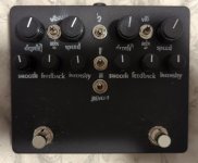
Haven't had a chance to record a demo, but I can assure you it does a thing. Audibly, even.

I'll try to get a video tomorrow before I leave, or when I get back in a couple days.

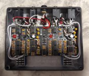
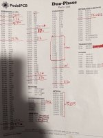
I included my build doc notes for the things I changed.
Changes apply to both sides
  • All the 3.9k, 39k, and 390k were swapped to 3.3, 33, and 330k respectively simply because I didn't have those exact values in my stash (actually, just didn't wanna dig for my seldom used parts values bin :ROFLMAO: )
  • R3 increased to up the input impedance a smidge
  • R7 reduced to 4.7k for more feedback. I felt this was a good value without it running off into full self-oscillation
  • R28 and R29 changed to closest values I had on hand
  • R30 has one leg lifted and attached to an SPDT to defeat the dry blend for Vibe tones
  • R34 lowered to 100r to essentially stop the sweep of the LFO
  • R35 lowered to better accommodate the raised value of the rate pot
  • R37 raised to 1k as I didn't have any 560r
  • C6-C11 raised to 10n for a bit more fat in the wet signal
  • C13 raised to 1n to take a bit more of the high end off when the feedback pot is maxed, and/ or when the speed pots are at their upper reaches
  • Rate pot increased to 1MA to go from slightly slower than stock speeds up to pseudo ring Mod tones in conjunction with R34 & R35. I used an audio taper to make it easier to dial in the midrange speeds
  • C18 increased because I have a lot more 22u tants on hand than 10u, and the value wasn't critical here
  • Both Trimpots have been made external. I've labelled the 10k Smooth, and the 1k Intensity
  • LDRs are 9203
  • LEDs are diffused Red Ultrabrights
  • IC6a/b are TL022 to help mitigate any ticking that might occur
  • Toggles added as a dry kill to R30 for vibe-like tones. With the asymmetrical waveshape of the LFO, this does some cool detuning stuff
  • Another toggle added to allow both outputs to be used independently. Though I may make this a full series/ parallel switch


orca-image-26259703.jpeg orca-image--132930381.jpeg orca-image--901268406.jpeg


As we're all aware, this is the best phaser. Build one, get swooshy

I'm most likely gonna be building another one of these when I return, but I'm gonna try the UniVibe Values for the caps in the phase stages
 
Last edited:
Wow, you really went for it!

  • Another toggle added to allow both outputs to be used independently.

I'm curious about this one. With switching / normalled jacks (using the diagram on page 6) you should be able to use the two outputs independently simply by plugging in to the two outputs.

Plugging in to Input 1 / Output 2 gives Phaser 1 > Phaser 2 series operation
Plugging in to Input 1 / Output 1 / Output 2 gives Phaser 1 on Output 1, and Phaser 1 > Phaser 2 in series on Output 2
Plugging in to Input 1 / Output 1 and Input 2 / Output 2 gives two independent phasers with no internal connection
 
Haven't had a chance to record a demo, but I can assure you it does a thing. Audibly, even

Most factual and to the point review ever.

Wow, you really went for it!

Plugging in to Input 1 / Output 2 gives Phaser 1 > Phaser 2 series operation

Plugging in to Input 1 / Output 1 / Output 2 gives Phaser 1 on Output 1, and Phaser 1 > Phaser 2 in series on Output 2

Plugging in to Input 1 / Output 1 and Input 2 / Output 2 gives two independent phasers with no internal connection

1FA8631F-F717-4179-84D7-E6E36584F8C5.jpeg
 
Wow, you really went for it!


I'm curious about this one. With switching / normalled jacks (using the diagram on page 6) you should be able to use the two outputs independently simply by plugging in to the two outputs.

Plugging in to Input 1 / Output 2 gives Phaser 1 > Phaser 2 series operation
Plugging in to Input 1 / Output 1 / Output 2 gives Phaser 1 on Output 1, and Phaser 1 > Phaser 2 in series on Output 2
Plugging in to Input 1 / Output 1 and Input 2 / Output 2 gives two independent phasers with no internal connection


The switch allows for plugging into input 1 and having the signal routed to each side independently. So 1 in, 2 out without phaser 1 running into phaser 2. Basically puts them in parallel for stereo operation

Its not terribly useful to me as I don't run a stereo setup, which is why I'm wanting to do the series/ parallel switch. Still working out the kinks to do that. So far the schemes I've tried have led to oscillation in one of the modes unless both circuits are active or bypassed

EDIT- Here's another build using the the 1 in 2 out switch. It also shows the wiring a bit better
But but, as a builder, it’s not about doing it, it’s about being able to do it.

1677957579319.gif
 
...With switching / normalled jacks (using the diagram on page 6) you should be able to use the two outputs independently simply by plugging in to the two outputs.

Plugging in to Input 1 / Output 2 gives Phaser 1 > Phaser 2 series operation
Plugging in to Input 1 / Output 1 / Output 2 gives Phaser 1 on Output 1, and Phaser 1 > Phaser 2 in series on Output 2
Plugging in to Input 1 / Output 1 and Input 2 / Output 2 gives two independent phasers with no internal connection
Me:
You! You've prototyped this. So tell me, Robert... How... is... it... WIRED?

Robert:
Uh. Hmm, well, uh, I don't know where the jacks are not stereo...

Me:
You're telling me you don't know how the stereo wiring goes?

Robert:
It wouldn't be inaccurate to assume that I couldn't exactly not say that it is or isn't almost partially incorrect.

Me:
So you *do* know how it's wired!

Robert:
On the contrary, I'm possibly more or less not definitely rejecting the idea that in no way with any amount of uncertainty that I undeniably...

Me:
Stop it!

Robert:
...do or do not know how the jacks shouldn't probably be wired, if that indeed wasn't how they aren't. Even if it wasn't wired up where I knew how it was, that'd mean I'd really have to know how it wasn't.

Me:
ENOUGH! I just want to be able make swooshy noises through my DuoPhase build... DGWVI, how do I do this?
 
Haven't had a chance to record a demo, but I can assure you it does a thing. Audibly, even.

I'll try to get a video tomorrow before I leave, or when I get back in a couple days.

I included my build doc notes for the things I changed.
Changes apply to both sides
  • All the 3.9k, 39k, and 390k were swapped to 3.3, 33, and 330k respectively simply because I didn't have those exact values in my stash (actually, just didn't wanna dig for my seldom used parts values bin :ROFLMAO: )
  • R3 increased to up the input impedance a smidge
  • R7 reduced to 4.7k for more feedback. I felt this was a good value without it running off into full self-oscillation
  • R28 and R29 changed to closest values I had on hand
  • R30 has one leg lifted and attached to an SPDT to defeat the dry blend for Vibe tones
  • R34 lowered to 100r to essentially stop the sweep of the LFO
  • R35 lowered to better accommodate the raised value of the rate pot
  • R37 raised to 1k as I didn't have any 560r
  • C6-C11 raised to 10n for a bit more fat in the wet signal
  • C13 raised to 1n to take a bit more of the high end off when the feedback pot is maxed, and/ or when the speed pots are at their upper reaches
  • Rate pot increased to 1MA to go from slightly slower than stock speeds up to pseudo ring Mod tones in conjunction with R34 & R35. I used an audio taper to make it easier to dial in the midrange speeds
  • C18 increased because I have a lot more 22u tants on hand than 10u, and the value wasn't critical here
  • Both Trimpots have been made external. I've labelled the 10k Smooth, and the 1k Intensity
  • LDRs are 9203
  • LEDs are diffused Red Ultrabrights
  • IC2 is TL022 to help mitigate any ticking that might occur
  • Toggles added as a dry kill to R30 for vibe-like tones. With the asymmetrical waveshape of the LFO, this does some cool detuning stuff
  • Another toggle added to allow both outputs to be used independently. Though I may make this a full series/ parallel switch


View attachment 43280View attachment 43281View attachment 43282


As we're all aware, this is the best phaser. Build one, get swooshy

I'm most likely gonna be building another one of these when I return, but I'm gonna try the UniVibe Values for the caps in the phase stages
Do you think it would be safe to use a 392K instead of the 390K? Or might see if I have a 330K. Looks great and I love the demo!
 
Just built a DuoPhase and I noticed a ticking noise even when bypassed. I may try replacing IC2 with a TL022. Does it control both LFOs?
 
No, it'd be IC6a and IC6b if you're going that route. Though, I've not actually had the ticking on any of my DuoPhase or Phase II builds 🤷‍♂️
So why did you replace IC2? Or is it both 2 and 6?

Edit: just looked at the schematic. IC6 makes sense. Still not sure why IC2?
 
Last edited:
Back
Top