chongmagic
Well-known member
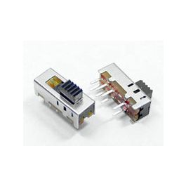
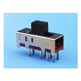
Is this the slide switch needed for the EMU Amp Simulator?
 www.taydaelectronics.com
Slide Switch 2P3T Through Hole 0.3A 50VDC
WEALTH METAL - Get It Fast - Same Day Shipping
www.taydaelectronics.com