Fingolfen
Well-known member
- Build Rating
- 4.00 star(s)
This is a build that has been languishing for a while, but I finally managed to get it done! I'd struggled through my first G-2 builds last year, and learned a lot about germanium diode leakage currents, voltage drops, and modifications necessary to compensate for them... so now it was time to apply that in making the "dino version" of the pedal!

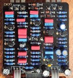
For this build, I immediately applied all of the learning from last year around the clipping diodes. In fact, the first components I added to these builds were the diodes themselves after I had verified the leakage current and voltage drop. From that point forward, the build was very straightforward. I'm using all 1% metal film resistors (Yageo and Speer). The film capacitors are WIMA and KEMET, with an emphasis on using 5% tolerance where possible (if I remember correctly the largest film capacitors are 10% tolerance). The electrolytic capacitors are all Nichicon. The transistors are BC549C like the original pedal, which is why they are all reversed relative to the silkscreen (which was set up for 2N5088 transistors).

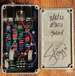
Because this is a buffered pedal, it actually makes use of all of the main PCB and daughter board PBC connections typical to the AionFX layout (most of the non-buffered pedals only actually use four of the connections). I'm using ribbon cable here because it is easier. There is a toggle switch on the 3PDT daughter board that lets the user switch between buffered and true bypass. I typically run my Cornish effects in buffered bypass. As with all AionFX layouts, this one uses a star ground to the input jack, and all of the connections to the audio and power jacks are insulated with heat shrink tubing.

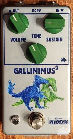
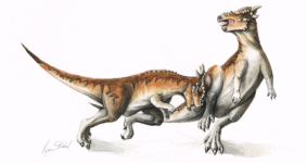
For the enclosure, we have a very suspicious looking pair of Gallimimus. I wonder what those two are up to? This pair of miscreants was painted by my wife - ADK - in the same medieval style she used for several dinosaur paintings. This is one of the last ones from that batch that I haven't showcased, but there are a couple more coming!
The pedal matches the sound of my previous G-2 builds, so there's no major surprise there. The G-2 always feels "darker" in tone than the other big muff clones I've built, but it definitely has its niche!
I'm honestly giving this project four stars at this point for a few reasons. First - I appreciate the fact that AionFX includes alternate resistor values to compensate for diodes with a lower forward voltage drop, but nothing is mentioned about the importance of leakage current - and this is listed as an "intermediate" build. I imagine a lot of people who have built this board have walked away disappointed. There is also a bit of a weakness in the board itself - the audio out trace on the back side of the board is very close to the edge of the board. I had one board (not the one above) where the trace was nicked enough to prevent signal from exiting the board. When in "active" mode, the resistance between the volume pot and the point where the audio signal left the primary PCB was over 50K ohms. I ultimately ran a wire directly from the pot to the PCB out location, and it fixed the problem immediately.
Original blog entry: https://steggostudios.blogspot.com/2023/03/finally-dino-themed-g-2-clone-no-really.html

For this build, I immediately applied all of the learning from last year around the clipping diodes. In fact, the first components I added to these builds were the diodes themselves after I had verified the leakage current and voltage drop. From that point forward, the build was very straightforward. I'm using all 1% metal film resistors (Yageo and Speer). The film capacitors are WIMA and KEMET, with an emphasis on using 5% tolerance where possible (if I remember correctly the largest film capacitors are 10% tolerance). The electrolytic capacitors are all Nichicon. The transistors are BC549C like the original pedal, which is why they are all reversed relative to the silkscreen (which was set up for 2N5088 transistors).

Because this is a buffered pedal, it actually makes use of all of the main PCB and daughter board PBC connections typical to the AionFX layout (most of the non-buffered pedals only actually use four of the connections). I'm using ribbon cable here because it is easier. There is a toggle switch on the 3PDT daughter board that lets the user switch between buffered and true bypass. I typically run my Cornish effects in buffered bypass. As with all AionFX layouts, this one uses a star ground to the input jack, and all of the connections to the audio and power jacks are insulated with heat shrink tubing.

For the enclosure, we have a very suspicious looking pair of Gallimimus. I wonder what those two are up to? This pair of miscreants was painted by my wife - ADK - in the same medieval style she used for several dinosaur paintings. This is one of the last ones from that batch that I haven't showcased, but there are a couple more coming!
The pedal matches the sound of my previous G-2 builds, so there's no major surprise there. The G-2 always feels "darker" in tone than the other big muff clones I've built, but it definitely has its niche!
I'm honestly giving this project four stars at this point for a few reasons. First - I appreciate the fact that AionFX includes alternate resistor values to compensate for diodes with a lower forward voltage drop, but nothing is mentioned about the importance of leakage current - and this is listed as an "intermediate" build. I imagine a lot of people who have built this board have walked away disappointed. There is also a bit of a weakness in the board itself - the audio out trace on the back side of the board is very close to the edge of the board. I had one board (not the one above) where the trace was nicked enough to prevent signal from exiting the board. When in "active" mode, the resistance between the volume pot and the point where the audio signal left the primary PCB was over 50K ohms. I ultimately ran a wire directly from the pot to the PCB out location, and it fixed the problem immediately.
Original blog entry: https://steggostudios.blogspot.com/2023/03/finally-dino-themed-g-2-clone-no-really.html


