master_hugues
New member
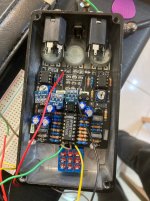
Dear all, I'm not getting any guitar signal through my effect, although I can hear a miniscule ticking in time with the rate LED. The LEDs light/blink as well, and I can control the rate. I can hear signal with an audio probe at IC3 pins 7 and 8, but not at pin 5. (Unless I'm reading the schematic wrong, I'd expect to hear it there.)
The JFETs are J201 SMDs mounted on mini-PCBs. I tested the soldering before installation and they seemed good. Also, the connections in the sockets seem firm.
Last, I haven't actually wired the off-board stuff properly yet. The LEDs are currently just resting in place (I drilled the holes too big for 3mm LEDs, so I'm waiting to buy bigger ones to solder them in), and I added a temporary jumper connecting the SW and GND pads on the bottom of the PCB. I'm sending signal in and out from the IN OUT pads down there as well, but not via a footswitch. Battery is hooked up to the + and - at the top of the board. I can wait until it's properly assembled to try again, but I would have expected it to work with this setup, temporary though it is.
I got these voltages on IC3 (LM13700):
1 -5.39
2 -5.53
3 -6.06
4 0.03
5 6.31
6 0.00
7 -0.01
8 -1.13
9 0.00
10 0.00
11 7.03
12 -6.02
13 0.19
14 0.00
15 0.00
16 -5.31
My voltages on the MAX1044 are a bit low, could it be due to powering it with a battery?
1 7.91
2 4.63
3 0.00
4 -3.03
5 -7.42
6 3.20
7 3.66
8 7.90
I tested the transistors too, can post those values if needed. I haven't tested the other op amps yet.
Any advice is greatly appreciated! Thanks in advance!
Last edited: