damianvila
Well-known member
Ok! time to document the building of this pedal. First of all, let me tell you a bit about myself and why I decide to create this.
I'm a Graphic/Web Designer, and I love Industrial Design. I started building pedals as a hobby, mainly using PCBs from Fuzz Dog in the UK. Then started learning how pedals work, reading sites like Electrosmash, Runoffgroove, etc. When Brexit happened, it became harder to keep buying PCBs from the UK, and I thought it may be a good opportunity to make my own PCBs, so that's how it all started. From that idea, Vila Effectors was born.
After a couple experiments, I started to think about something I would like to have in a pedal. Since I normally use pedal pairs I love (like a FET booster with an Electra Distortion, for example) I thought it would be a good idea to create double pedals with combinations that I find interesting. I wanted it to have a late 70s/early 80s vibe, and I took inspiration from Mazinger Z (or rather, its enemies), and that's how the "Mechanical Beasts" series started.
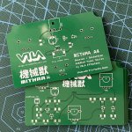
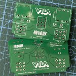
My goals for this series is not to design any novel circuit (I think I have not enough knowledge to create anything particularly original, so it's useless for me to go that way), but to make combinations I like from existing classic circuits, with minimal to no modification. I also want the most professional finish a hobbyist can make (so UV enclosure printing), and a very important one to me is to get rid of as many cables as possible inside the pedal. I use PCB + SMD for the construction.
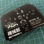
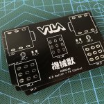
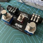
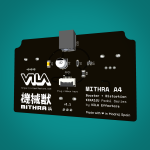
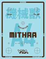
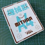
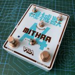
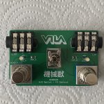
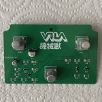
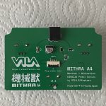
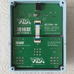
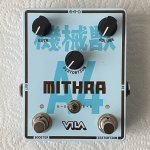
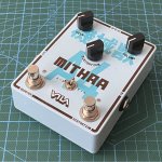
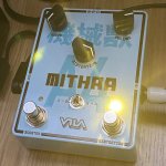
Mithra A4 (the names are styled to resemble the Mechanical Beasts from Mazinger) is the first in this series, and it's a FET booster (in this case I'm using the AMZ booster) and an Electra Distortion in a 1590BB enclosure, with independent switches and LEDs and an order toggle switch.
Although I've been using EAGLE for most of my past PCBs, I switched to EasyEDA for these pedals, since Autodesk is getting rid of EAGLE in a few years.
So, first things first. Here you have the schematics:
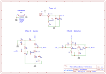
Nothing too fancy here, I just added a pot to the Electra and changed the clipping section to Schottky diodes, instead of Germaniums.
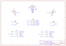
Here's the switches schematic:
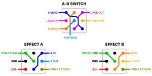
The switches are wired in this way:
I'm a Graphic/Web Designer, and I love Industrial Design. I started building pedals as a hobby, mainly using PCBs from Fuzz Dog in the UK. Then started learning how pedals work, reading sites like Electrosmash, Runoffgroove, etc. When Brexit happened, it became harder to keep buying PCBs from the UK, and I thought it may be a good opportunity to make my own PCBs, so that's how it all started. From that idea, Vila Effectors was born.
After a couple experiments, I started to think about something I would like to have in a pedal. Since I normally use pedal pairs I love (like a FET booster with an Electra Distortion, for example) I thought it would be a good idea to create double pedals with combinations that I find interesting. I wanted it to have a late 70s/early 80s vibe, and I took inspiration from Mazinger Z (or rather, its enemies), and that's how the "Mechanical Beasts" series started.
My goals for this series is not to design any novel circuit (I think I have not enough knowledge to create anything particularly original, so it's useless for me to go that way), but to make combinations I like from existing classic circuits, with minimal to no modification. I also want the most professional finish a hobbyist can make (so UV enclosure printing), and a very important one to me is to get rid of as many cables as possible inside the pedal. I use PCB + SMD for the construction.
Mithra A4 (the names are styled to resemble the Mechanical Beasts from Mazinger) is the first in this series, and it's a FET booster (in this case I'm using the AMZ booster) and an Electra Distortion in a 1590BB enclosure, with independent switches and LEDs and an order toggle switch.
Although I've been using EAGLE for most of my past PCBs, I switched to EasyEDA for these pedals, since Autodesk is getting rid of EAGLE in a few years.
So, first things first. Here you have the schematics:

Nothing too fancy here, I just added a pot to the Electra and changed the clipping section to Schottky diodes, instead of Germaniums.
Here's the switches schematic:

The switches are wired in this way:


