SOLVED Muffin Fuzz Triangle No Works...

Coda

Well-known member
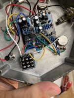
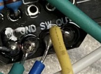
Just finished the Triangle Muff build and ran into that chestnut of an issue: no sound. I get a bypass signal, but nothing when I click the pedal on, other than a bit of static from the volume pot. I’ve gone over the board a few times and everything looks correct. I either missed something simple, or maybe my switch is faulty. Any ideas?
 

Attachments

  • A7D24E8E-069A-4A86-B82E-F6F259EA242B.jpeg
    A7D24E8E-069A-4A86-B82E-F6F259EA242B.jpeg
    2.3 MB · Views: 28
Have you tried a signal probe to guesstimate where the signal fails to pass?

And is there a reason for the two missing resistors and the missing cap?
 
Have you tried a signal probe to guesstimate where the signal fails to pass?

And is there a reason for the two missing resistors and the missing cap?

I have not probed the signal...that would be a new talent to learn. The missing components are per the build guide.
 
First step of debugging is to check the voltages on transistor pins. Another thing to do is test the signal nets with a continuity tester to make sure none are grounded.
 
Is the board touching the case? you only have one pot supporting the top right of the board, you need something on the left side to prevent the board from touching the case and shorting out.
 
Is the board touching the case? you only have one pot supporting the top right of the board, you need something on the left side to prevent the board from touching the case and shorting out.
Good call, but there is about a centimeter of clearance underneath. It’s not evident in the photo, but I have it tightened down so that the lower corner just grabs the pot.

I re-flowed all of the solder joints and there’s no difference. From poking around, I get a buzz when I touch the output jack, as well as the output side of the breakout board. No sound from anywhere else...
 
I believe this is the Triangle Version, Correct ?
I was curious about the the Solder around R16 - 820, Looks weird& It looks like you have used 820K?
Check R5-820 ohms also!
UPDATE : I think R11-150 is incorrect, It appears to be 150K!
Here is a Resistor Calculator to Check your values
Just click on Bands for 5 Colours:
 
Last edited:
I believe this is the Triangle Version, Correct ?
I was curious about the the Solder around R16 - 820, Looks weird& It looks like you have used 820K?
Check R5-820 ohms also!
UPDATE : I think R11-150 is incorrect, It appears to be 150K!
Here is a Resistor Calculator to Check your values
Just click on Bands for 5 Colours:
What is this at R16 - 820 , Is the Board missing the Solder pad? Silver, Red, Black, Orange, Brown = 820K
View attachment 6751

A regular eagle eye. It appears I did grab the wrong resistors. I will swap them out and see how it goes.
 
Back
Top Bottom