SOLVED Pathogen build, no audio, no led

Hi
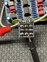
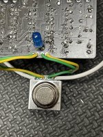
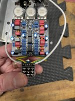
I have a pathogen build with a 3 pdt stomp with a mini pcb board

Pass thru works ok
Stomp engaged, no led, no output

Pcb + to mini pcb IN shows-9.29v

I suspect the 3pdt but it is unclear what the proper set up is. Not sure what to look for in the switch.

Attaching a pic

Appreciate any advice.
 

Attachments

  • IMG_2161.jpeg
    IMG_2161.jpeg
    511.9 KB · Views: 12
  • IMG_2159.jpeg
    IMG_2159.jpeg
    479.6 KB · Views: 9
Here is a clear pic. The yellow and green is a bit confusing
Lol I think it put me in a trance or something. I would try testing continuity at the wires for the gnd and switch. You should have continuity with the effect switched on. If not I would try reflowing the middle lug as it looks like it could be a little shy on solder. In general on the tabs on the switch you should have continuity from the middle row to the top row tabs one way and the middle to the bottom the other.
1702846155898.png

But you will also have continuity between pins 1 and 6 and 3 and 9 as they are connected on the breakout board.
 
Lol I think it put me in a trance or something. I would try testing continuity at the wires for the gnd and switch. You should have continuity with the effect switched on. If not I would try reflowing the middle lug as it looks like it could be a little shy on solder. In general on the tabs on the switch you should have continuity from the middle row to the top row tabs one way and the middle to the bottom the other.
View attachment 63535

But you will also have continuity between pins 1 and 6 and 3 and 9 as they are connected on the breakout board.
I verified that there is continuity between middle and bottom then switch on middle and top.

Pb
 
Note. I am testing with the multimeter buzzer between the lugs just to be clear. I guess this rules out the switch
I think the switch is probably good then. I would check at the wires for ground and switch too just to make sure it is going through the joint. Otherwise I would start tracing the power from the inlet to the LED. Go black to ground and then start with red at the DC input. It's possible the wires to the power supply are backwards. Some of the DC plugs have a bypass connector that only has continuity with the switch unplugged also.
 
Back
Top