Sandspur no signal?

drgonzo1969

Well-known member
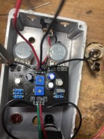
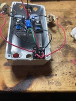
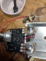
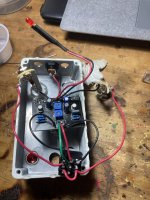
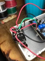
Troubleshooting this Sandspur. I’ve double checked wiring and component values, gave it a scrub. The LED lights up but no signal when effect is on. I’ve tried all positions with the bias trim. Bypass signal is good. Anybody see anything wrong?
 

Attachments

  • image.jpg
    image.jpg
    443.9 KB · Views: 31
  • image.jpg
    image.jpg
    397.3 KB · Views: 32
  • image.jpg
    image.jpg
    388.3 KB · Views: 31
  • image.jpg
    image.jpg
    499.2 KB · Views: 33
Your switch wiring is wrong. The jumper is in the wrong place from the lower row of pins on the switch. It should go from the lower left to the lower right. Try that first and then see if there are any other issues.

I would also try and reflow some of those joints.
 
It goes backwards into the lug. Haha I did a double take on that too when I dug this circuit out of my non-functional pile. I think you are right about reflowing some of these joints tho.
 

Attachments

  • image.jpg
    image.jpg
    302.9 KB · Views: 17
The connections look right to me. Bad switch maybe? You could try testing for continuity between the lugs that go to your audio jacks and the ones above where they switch to the board.
 
Q1 E-0v
B-0.26v
C-0.93v

Q2 E-0.29v
B-0.94v
C-0.29v
The collector voltages definitely seem low to me. Especially for Q2, you won’t have a working transistor with the collector at a lower voltage than the base (I think the transistor may be in cutoff).
Q1 base may also be too low but I’m not sure what the intended voltage should be.
 
  • Like
Reactions: fig
I went back and reflowed all the solder joints and tried to bias Q2 but the trim pot has no effect on the voltages when turned. I checked the continuity on between pcb and switch and it was good. I tested with knobs at 12 and fully cranked and i got the same voltages on all positons. this was one of the first pcbs i built and i didnt socket the bc108s. i have some more bc 108s. should i pull these and try new ones or does this sound like something else maybe?
 
Last edited:
Before replacing components you need a better diagnosis. Did you visually verify all component values? Did you check for continuity? If all that is good, I would start audio probing to see where the signal path breaks.
 
  • Like
Reactions: fig
okie dokie smokies. I fired up the audio probe and the signal is good from input to switch and from switch to PCB. but I lose signal on the second hole for R1 (100k). I tried two different 100k resistors last night (both verified on component tester) and still nothing on second hole of R1. so today tried one more 100k resistor and still nothing. I reflowed the adjacent resistors and cleaned up the board with brush and rubbing alcohol and im still not getting signal. Any ideas?
 
I wouldn't expect signal on the far side of R1. Sounds as if you have sound on the base of Q1. Do you get sound at the base of Q2? Then what about the collector of Q2? Then follow the resistor chain R3 - Bias - Sundial. Then you are only left with C3 and the volume pot. I wouldn't go replacing parts until it is pretty clear what is wrong and that a part needs to be replaced. Too much heating and reheating can damage the PCB. Work out for sure what is wrong if you can and then replace.
 
dang! i knew i was doing something wrong. first time with the audio probe. lesson learned hahaha. ok so i have signal on Q1 base but no signal on Q2 base or collector.
 
OK, by the look of it Q2 collector should be biased to between about 4.5V and 6.5V with the sundial pot set to minimum. Looking at the above, your bias is set very low. Have you tried to bias it?
 
You won't get audio signal across the bias trimmer unless the transistor is properly biassed. Measure the voltage at the collector with your multimeter and adjust the trimmer until it is somewhere in the 4.5 - 6.5 V range (depends on taste). If you aren't getting any signal across there than there may be another problem, but get the bias voltage set correctly to eliminate that variable. If you can't get it set to the correct voltage range then that will need t obe looked at.
 
You won't get any voltage change on a bias trimmer if there's no path to ground, like through the emitter, the fuzz pot, and C2. Are you measuring the voltage from Q2 collector to ground?
 
I've got 0.29v on collector of Q2. I have the negative clip of the multimeter attached to ground of input jack and then i put the positive on the collector of Q2.
 
Last edited:
Back
Top