jesuscrisp
Well-known member
So, I'm no Chuck D. Bones around here so I kind of expect this to be mostly ignored, but anyway...
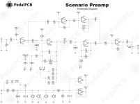
Seeing the schematic of the Scenario Preamp, which is based on the Cornerstone Gladio SC... which is basically a Jan Ray with miniscule changes and a clean blend, I couldn't help but think that this has no right being built as wasteful as it is. And this by no means is giving flack to Robert, who just provides traces as accurately as possible for all us pedal-hungry bastards out here.
What do I mean by wasteful?
First and foremost I'd argue it uses twice the op amps it needs without any benefit at least in my eyes.
Does a clean blend really need to invert polarity of the signal twice only to end up in a mixing amplifier anyway? Do you really need 2 different op amp buffered Vref points? I'd argue no on both. And then I saw another couple of little opportunities so save some parts without affecting tone or function, and while at it why not also just go ahead and place the bass knob on the outside and make the low gain tones more easy to dial in?
So here I proudly present: The Gladiolo, a minimalist Gladio SC that (presumably, haven't tested it yet) does the same thing with fewer parts and (at least in my opinion) to some degree also more intelligently and adding some personal tweaks, having built Timmy/Jan Ray style circuits before.
Clean blend: The original has a clean blend that is both cool in idea, yet also kinda stupid in execution. What it essentially does is amplify the clean signal in parallel with the overdrive circuit and mix it with a summing amplifier (IC1.2 in the Scenario). I like the functionality, as I personally don't see myself dialing in more clean signal than dirt with a blend and this kind of blend really just allows you to bring back some dynamics into your tone instead of having too blatant of a "dirt over clean" sound. But why is it stupid? Mainly because it wastefully uses an entire dual IC for an inverting buffer followed by an inverting gain stage that controls the amount of clean signal going into the summing op amp. Why not just use the clean signal coming off the buffer straight and use the summing op amp for amplification of it? Which is exactly what I did in the schematic below. This saves us a whole TL072. Now the mixing amplifier amplifies the clean signal up to about 25 dB, but this can be limited by increasing R12, as the original only goes up to 20 dB.
Saving more parts: C5 in the Scenario schematic, especially without a resistor between itself and C4, seems pretty damn useless to me. Same goes for the entirety of IC4 (and having 2 Vref points in a low gain circuit like this). This saved us a second TL072, so take both of them and build another Kliche or something. For the clipping diodes, inspired by Paul Cochrane's Tim and Timmy, connecting the 2 pairs of diodes in the middle gives us the option to use 1 or 2 diodes per side, while only requiring a total of 4 instead of 6. I can't speak for what exactly the tonal difference is between having the connection in the middle vs not, but feel free to correct me if it's a stupid idea.
Personal preferences: I prefer my Timmies to have the bass knobs on the outside, because it is in fact very useful to adjust to different guitars or amps, so C50K pot for the most usable taper in this kind of circuit. A1M for the gain pot for a compromise between having too little wiggle room for low gain tones and the circuit feeling too low gain. As there is a buffer, R3 can be basically any value between 10K and 470K, but there really is no use to have 1M here as in the original, especially not with a BJT input IC like the 4558. R11 I just added because it is considered good design to have some series resistance with the volume pot at the end like this. I might also swap the volume pot with A10K as the Timmy/Jan Ray isn't too quiet of a circuit and I dislike pedals that hit unity gain at 9 o'clock or below.
I do consider drawing up a vero layout to test it, or even do PCBs if anybody is interested, as well as posting further reworks and modifications of pedals.
Also open to any discussion or corrections.

Cheers!
Seeing the schematic of the Scenario Preamp, which is based on the Cornerstone Gladio SC... which is basically a Jan Ray with miniscule changes and a clean blend, I couldn't help but think that this has no right being built as wasteful as it is. And this by no means is giving flack to Robert, who just provides traces as accurately as possible for all us pedal-hungry bastards out here.
What do I mean by wasteful?
First and foremost I'd argue it uses twice the op amps it needs without any benefit at least in my eyes.
Does a clean blend really need to invert polarity of the signal twice only to end up in a mixing amplifier anyway? Do you really need 2 different op amp buffered Vref points? I'd argue no on both. And then I saw another couple of little opportunities so save some parts without affecting tone or function, and while at it why not also just go ahead and place the bass knob on the outside and make the low gain tones more easy to dial in?
So here I proudly present: The Gladiolo, a minimalist Gladio SC that (presumably, haven't tested it yet) does the same thing with fewer parts and (at least in my opinion) to some degree also more intelligently and adding some personal tweaks, having built Timmy/Jan Ray style circuits before.
Clean blend: The original has a clean blend that is both cool in idea, yet also kinda stupid in execution. What it essentially does is amplify the clean signal in parallel with the overdrive circuit and mix it with a summing amplifier (IC1.2 in the Scenario). I like the functionality, as I personally don't see myself dialing in more clean signal than dirt with a blend and this kind of blend really just allows you to bring back some dynamics into your tone instead of having too blatant of a "dirt over clean" sound. But why is it stupid? Mainly because it wastefully uses an entire dual IC for an inverting buffer followed by an inverting gain stage that controls the amount of clean signal going into the summing op amp. Why not just use the clean signal coming off the buffer straight and use the summing op amp for amplification of it? Which is exactly what I did in the schematic below. This saves us a whole TL072. Now the mixing amplifier amplifies the clean signal up to about 25 dB, but this can be limited by increasing R12, as the original only goes up to 20 dB.
Saving more parts: C5 in the Scenario schematic, especially without a resistor between itself and C4, seems pretty damn useless to me. Same goes for the entirety of IC4 (and having 2 Vref points in a low gain circuit like this). This saved us a second TL072, so take both of them and build another Kliche or something. For the clipping diodes, inspired by Paul Cochrane's Tim and Timmy, connecting the 2 pairs of diodes in the middle gives us the option to use 1 or 2 diodes per side, while only requiring a total of 4 instead of 6. I can't speak for what exactly the tonal difference is between having the connection in the middle vs not, but feel free to correct me if it's a stupid idea.
Personal preferences: I prefer my Timmies to have the bass knobs on the outside, because it is in fact very useful to adjust to different guitars or amps, so C50K pot for the most usable taper in this kind of circuit. A1M for the gain pot for a compromise between having too little wiggle room for low gain tones and the circuit feeling too low gain. As there is a buffer, R3 can be basically any value between 10K and 470K, but there really is no use to have 1M here as in the original, especially not with a BJT input IC like the 4558. R11 I just added because it is considered good design to have some series resistance with the volume pot at the end like this. I might also swap the volume pot with A10K as the Timmy/Jan Ray isn't too quiet of a circuit and I dislike pedals that hit unity gain at 9 o'clock or below.
I do consider drawing up a vero layout to test it, or even do PCBs if anybody is interested, as well as posting further reworks and modifications of pedals.
Also open to any discussion or corrections.
Cheers!