Stripboard Troubleshoot - MXR Headphone Amp

BuddytheReow

Breadboard Baker
Hey Guys,

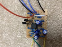
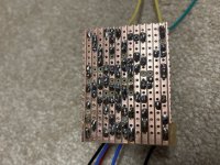
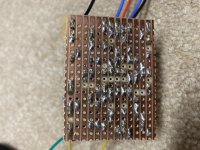
Need a little help with this stripboard build. I want to attach this one right after a 6 Pot EQ board for some portable practice, but am not getting any sound out of this. My voltages are as follows. The build calls for 2n4401 and 2n4403, but I substituted with 2n3904 since I had them. With an audio probe I get signal into IC pin 3 and occasionally out pin 6. I tried swapping out the TL071 but no change. I did swipe my solder iron down the tracks to get any potential solder off, but I'm posting some pictures just in case. I couldn't test the 10m and 2m resistors since my multimeter is cheap and can't measure that big, but the color rings on them match what the value is supposed to be.

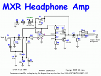
Heres a link for the schematic. http://www.generalguitargadgets.com/pdf/ggg_mxr_hpamp_sc.pdf


IC Pin 1 - 0.25
IC Pin 2 - 3.4
IC Pin 3 - 1.11
IC Pin 4 - 0
IC Pin 5 - 0
IC Pin 6 - 8.27
IC Pin 7 - 9
IC Pin 8 - 0

Q1 B - 4
Q1 C - 9
Q1 E - 3.5

Q2 B - 0
Q2 C - 2.8
Q2 E - 3.5

Diodes 2.3v and 1.7v on each side

1611955188230.png
 

Attachments

  • B0967E2D-9D39-46FF-B491-5D9C374551E5.jpeg
    B0967E2D-9D39-46FF-B491-5D9C374551E5.jpeg
    130.3 KB · Views: 22
  • E3C65ECB-997E-47B2-8DEF-F046012FE48C.jpeg
    E3C65ECB-997E-47B2-8DEF-F046012FE48C.jpeg
    154 KB · Views: 25
  • F110ED8F-1E05-48A1-A70E-A34DDB7C84FA.jpeg
    F110ED8F-1E05-48A1-A70E-A34DDB7C84FA.jpeg
    126.4 KB · Views: 37
  • 1611955214354.png
    1611955214354.png
    71.2 KB · Views: 40
Last edited:
Just threw a 2n3906 in to q2. No change. Also no signal coming out of pin 6 on the IC. Could I have fried my chip? Couldn’t be the socket since I have power going to pin 6
 
Last edited:
I updated the voltages above. I decided to test it one more time. If I bridge my probe (it’s a multimeter lead) across pins 5 and 6 the circuit fires up, although very gain-y.

Hmm...any ideas? Is it my chip?
 
The first bit is similar to a micro amp

You've got power to pin 7 and Q1 collector which looks correct from the schematic

Check what voltage you get on pin 3 with the IC out of socket
 
It looks to me from the schematic that pin 6 should be biased to 4.5V, but you are reading pretty much one diode drop from 9V on that pin. That suggests a short from 9V across r6 to me.
 
Look for tiny shorts or debris between strips and at the cuts, that's usually what keeps my Vero boards from working.

Let's review the voltages:
IC1-1 don't care
IC1-2 should be 4.5V
IC1-3 you can't measure this with your meter because of R1.
IC1-4 ground
IC1-5 don't care
IC1-6 should be near 4.5V
IC1-7 power
IC1-8 don't care

I think the IC is ok and something else in the circuit is messing things up. With pin 6 at 8.27V, Q1 & Q2 emitters should also be near 8.27V and they're not.

Q1 looks ok
I think you have B & C swapped when you reported voltages on Q2, check them again.

I do not understand the diode voltages you reported.

Check the voltage on the + side of C4, should be 4.5V.

Have you verified that the Vero layout matches the schematic? Many of the ones I've checked had errors. Make sure R6 is the correct value, is installed and soldered correctly.
 
Last edited:
Thanks for helping, @Chuck D. Bones . In no particular order:

My mistake with Q2 voltages. They are
E- 3.5v
B- 2.8v
C- 0v


R6 is correct

There are some differences in the schematic vs layout. I'm assuming r4 (22m) was replaced by a 10m resistor, but its a pulldown one so im not too concerned with that.

Another thing I noticed is that Q1 and Q2 get quite warm after a few minutes. Definitely not a good sign, but am hoping whatever the other problem is will fix it.

C4 (which I think is circled below based on the schematic) voltage reads 9v, which tells me the divider (also circled) isnt working, however the 10k resistors are measuring correctly.
1612363846592.png
 
VISUAL INSPECTION!

Use magnification and good lighting.

Q1 & Q2 are going to run hot because their bias is not well controlled. You could try using schottky's for D1 & D2, that would help. Not to burst your bubble or anything, but this is not a great circuit and you'd be better off using an LM386 to drive headphones or a small speaker.
 
Are you saying to swap out the tl071 for a lm386? Or are you saying a circuit based on a lm386 will work better. I will run my iron down all the tracks and use a small utility knife if need be to clean up. If I have to scrap this, then oh well. Its stripboard so I would only be getting rid of $5-8 tops. I can re use the trannies, pot and IC for something else. I was really hoping this could work and put it after a cab sim or eq board for some good practice time.
 
Last edited:
Are you saying to swap out the tl071 for a lm386? Or are you saying a circuit based on a lm386 will work better. I will run my iron down all the tracks and use a small utility knife if need be to clean up. If I have to scrap this, then oh well. Its stripboard so I would only be getting rid of $5-8 tops. I can re use the trannies, pot and IC for something else. I was really hoping this could work and put it after a cab sim or eq board for some good practice time.
I'm saying a circuit based on an LM386 will work better because the LM386 is a self-contained mini power amplifier. You'll have to search for a headphones amp layout that uses an LM386. I didn't see anything on Guitar FX Layouts, but I'm sure there are Vero layouts for such a thing. Maybe someone on this forum is aware of one. Here's the datasheet, it has example circuits.
 

Attachments

  • LM386.pdf
    1.3 MB · Views: 5
Cool. Is the datasheet helpful? The only downside to the LM386 is the input impedance is only 50K. Pedals will have no trouble driving it, but if you run a guitar straight in it could alter the tone a bit.
 
Back
Top